ITER NEWSLINE
-
Feeders
Delivering the essentials
Feeders | Delivering the essentials
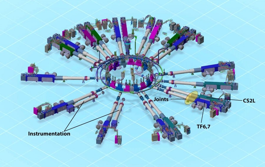
Like a circle of giant syringes all pointing inward, the feeders transport and deliver the essentials to the 10,000-tonne ITER magnet system—that is, electrical power and cooling fluids. Twenty-one feeders, each dedicated to a specific coil or pair of coils¹ are installed in the gallery at the second basement level (B2) of the Tokamak Building; ten others are located five floors above at the L3 level. All have been provided by China. Installation of the massive, maddeningly complex systems, began in November 2018 with the insertion of a captive "cryostat feedthrough"—the 10-metre-long section of a feeder section—at the bottom of the Tokamak Pit.

Of 21 feeders installed in galleries at the B2 level of the Tokamak Building, two accommodate high and low-voltage instrumentation cables and hardware. Ten other feeders are located five floors overhead, at the L3 level.
Over the ensuing years the main elements that constitute a feeder were progressively installed in the galleries of the Tokamak Building. At the B2 level, 16 coil terminal boxes the size and weight of a city bus, and 18 cryostat feedthroughs that pass through the bioshield and cryostat to be connected to the coils are now fully installed and welded. At the L3 level, 6 coil terminal boxes and 8 cryostat feedthrough have been lifted and placed in long-term temporary positions, pending the insertion of the cryostat's upper cylinder.

At the second basement level (B2) of the Tokamak Complex, highly skilled workers from the CNPE consortium are finalizing the joints on the feeder connected to the lowest central solenoid module (CS2L).
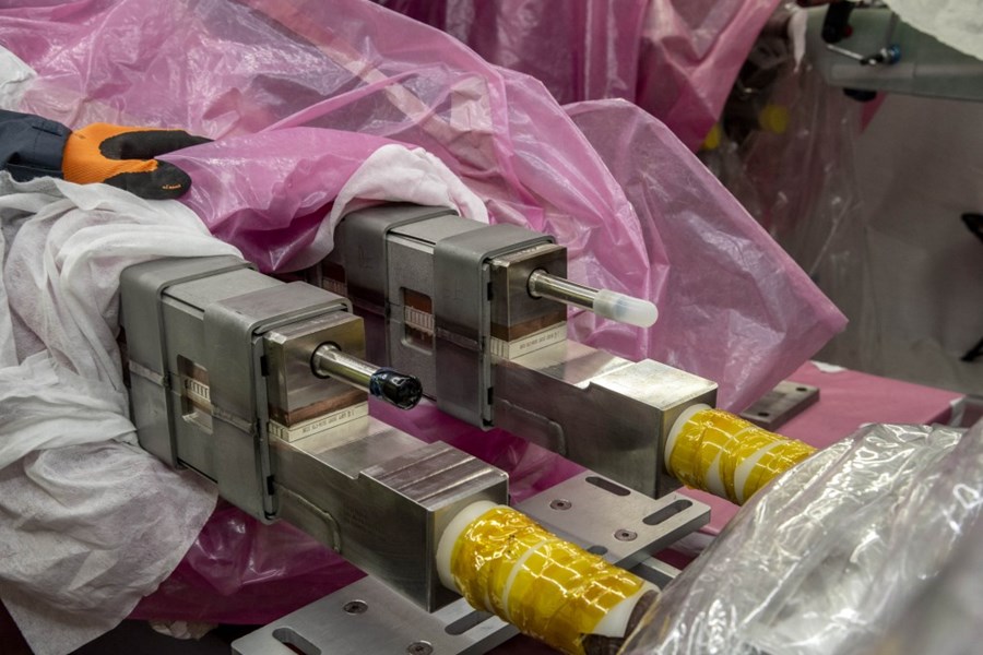
One of the most delicate operations in the installation process is the creation of the superconducting joints² that provide electrical connections between the busbar at the exit of the coil terminal boxes and those at the entrance to the cryostat feedthroughs. Teams of highly skilled workers, having qualified via robust training program, are presently working on joint assembly at the B2 level of the Tokamak Building.
In the image above, workers from the CNPE consortium are finalizing the joints on the feeder connected to the lowest central solenoid module (CS2L). Their job consists in positioning high-pressure fiberglass panels around the finalized joint in order to form a "hard shell," or mold, into which epoxy resin will be poured to ensure electrical insulation.

The criticality of the superconducting feeder joints stems from the fact that they can only be truly tested once the machine is up and running. Hence the exceptionnaly demanding qualification programs for the technicians who realize joint assemblies.
As a joint's electrical performance can only truly be put to the test at the ITER operating temperature of 4 K (minus 269 °C) and operating current (up to 70 kA)—and these conditions will only be reached when the machine is commissioned—the quality of the work performed is of paramount importance for the project.
¹Of the 31 feeders to be installed (21 at lower level, 10 at upper level), two are exclusively dedicated to instrumentation signals and three to the cooling of coil structures. All others carry current and coolant to magnets.
²The solutions that were developed for the joints bring their electrical resistance to an extremely low value—in the nano-ohm (nΩ) range. Despite this tiny amount of resistance and resulting small amount of heat generated, they can still be called "superconducting."
See also: H. Kim et al., "Progress on First-of-a-Kind Feeder Superconducting Machine Joints and Surrounding Structure Assembly in ITER Magnet System," in IEEE Transactions on Applied Superconductivity, vol. 34, no. 5, pp. 1-4, Aug. 2024, Art no. 4205104, doi: 10.1109/TASC.2024.3366158.
return to the latest published articles