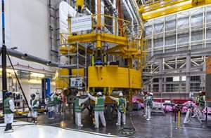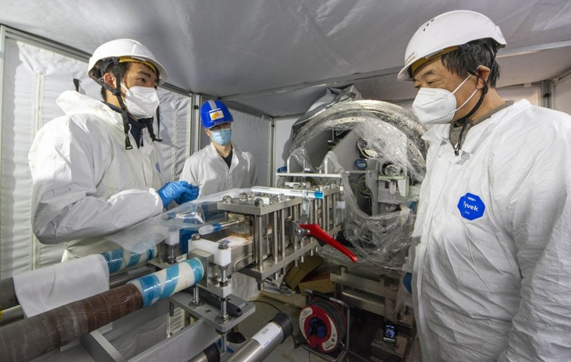
At the B2 (lower basement) level of the Tokamak Building, trained specialists are assembling the first feeder joint connecting the superconducting busbars from two feeder segments, the coil terminal box and the cryostat feed-through. This connection will feed 70 kA electrical current to toroidal fields coils #12 and #13.
Answering this question is especially critical when it comes to assembling the superconducting joints that connect the high current feeding lines (busbar) to the magnets through the magnet feeders. Approximately 300 superconducting feeder joints need to be created as part of assembling the feeders, which are

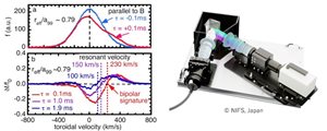
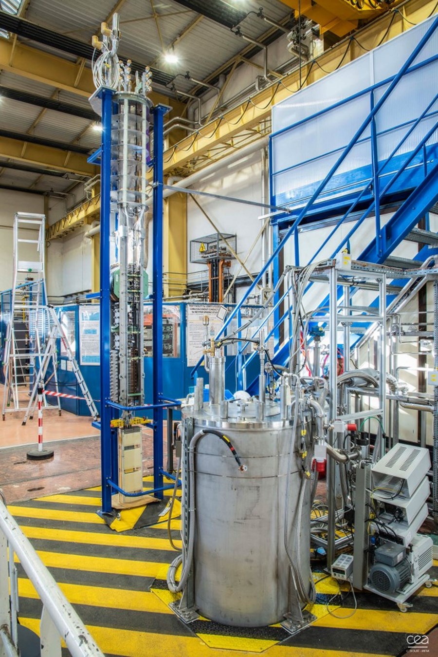
In the SELFIE installation, joint production proof samples will be tested in temperature and current intensity that are representative of ITER operating conditions. The 6.2-metre-tall installation, of which only the upper part is visible in this image, is located next door at CEA-Cadarache. Its superconducting transformer, power supply and entire control and protection system was designed and built at the University of Twente in the Netherlands in collaboration with the Foundation SuperACT. The system was successfully commissioned in January 2022. Photo Christophe Roux - CEA
It is of paramount importance that the qualified specialists maintain a stable and verifiable level of performance throughout the four years that joint assembly operations will last. In this perspective, and within the framework of the