Logo
You're currently reading the news digest published from 31 October 2016 to 7 November 2016.
Featured (5)
Of interest (2)
Press (2)
Featured
Helium_leaks_Mitul_close_up_1_small.jpg

Cracks in welds? Helium will tell

In a 6,000-square-metre workshop on site, the Indian Domestic Agency is assembling the cryostat—a huge vacuum containment vessel that is also the single largest component of the ITER machine. 
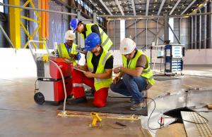
The first welding activities began in September 2016 on the cryostat base (tier 1). Today, on the perfectly polished circular surface of the lower base section, welders have given way to specialists in leak detection.   Their role is crucial: once assembled, the 8,500 m³ vacuum chamber must be absolutely leak tight. The challenge is considerable and begins with the quality of the welds. Every millimetre of vacuum-facing weld joints must be leak-tested before commissioning.   In tier 1 of the cryostat base alone, over 100 metres of weld must be tested. The process—although simple in its principle—is meticulous to implement.   If there's a crack in a weld crossing the vacuum boundary, no matter how small, it's a problem. And to detect it, something equally as small must be employed. "We use helium to detect cracks, which is as safe as it is inert¹ and whose atoms are among the smallest² of the periodic table," explains Liam Worth of the ITER Vacuum Section. "Helium atoms also have a have low viscosity—they are 'slippery.'"   Procedures for leak testing of the cryostat welds were prepared by Larsen & Toubro Ltd, the Indian company that manufactures the component; they were submitted to and validated by ITER-India and the ITER Organization and are being implemented by Larsen & Toubro's German contractor MAN.   Acting as "witnesses," representatives of ITER India and Larsen & Toubro are present at every stage of the process.   Helium is injected into a box positioned on the underside of the component, which looks a lot like the one on the surface. In order to cover all welds, the operation is repeated every metre with several centimetres of overlap. The helium leak testing method utilized consists of creating a "vacuum box" to cover the surface of the weld under test. In a similar fashion a "helium box" is created directly underneath, on the opposite side of the weld. These thin, one-metre long boxes are made of aluminium foil and sealed with vacuum-compatible tacky tape.   Once air has been evacuated from the vacuum box, helium is injected under pressure into the helium box below. If there is a crack the tiny, light and "slippery" atoms will work their way through the defect to end up in the vacuum box on the steel plate's surface. And because the upper box is connected to a highly sensitive mass spectrometer, any helium atom that has passed through the weld into the vacuum box will be detected.   In order to cover all welds, the operation will be repeated every metre with several centimetres of overlap.   Finding a leak would be a "major issue" ... but also a fixable one. "Using the same leak detection technique, but with a much shorter box, we would first need to pinpoint the leak's location," explains Liam. "Repair would then consist of grinding out the faulty weld all the way through the steel plate, then re-welding and testing."   1-The hydrogen atom is smaller but hydrogen gas is explosive. 2-The atomic radius of helium is about three million times smaller than that of a human hair.
TBM_PC_Oct_2016_small.jpg

Committee reviews progress on test blanket modules

On 19-21 October, the Committee charged with the governance of the Test Blanket Module (TBM) program convened at ITER Headquarters for its 16th meeting. The TBM Program Committee meets twice a year to review the various aspects of the ITER TBM program and to advise the ITER Council on its implementation. The three-day meeting kicked off with a presentation by ITER Director-General Bernard Bigot on recent project progress and achievements and on the new organization set in place for the construction of the ITER machine and plant. ITER's planned research activities were also discussed—including an incremental "phased" approach and its impact on the TBM program.   In ITER, six technological solutions for a tritium breeding blanket (in the form of test blanket modules plus ancillary systems) will be operated and tested for the first time.   The Program Committee noted that the test blanket systems are expected to be installed during the second pre-fusion power operation phase. The exact duration for this phase and possible impact on the TBM program will be analyzed in the coming months. Activities for the test blanket systems are progressing well in the ITER Members. Conceptual designs have already been approved for two systems—the helium-cooled ceramic breeder (developed in China), and the helium-cooled ceramic reflector (developed in Korea)—and for both of them the kick-off meeting for the preliminary design phase was held in early 2016. The conceptual designs of the remaining four test blanket systems are expected to be approved by the end of this year.   This will represent a major milestone in the TBM program since it will conclude the conceptual design phase for all the involved systems and components.   The connection pipes of the test blanket systems are captive components that have to be delivered well before First Plasma with due dates spread between 2020 and 2022. To respect need dates, significant progress has been made on their revised conceptual design and a contract with a Spanish consortium has been signed to perform the final design. An agreement covering the definition of responsibilities during the assembly, testing and commissioning of the connection pipes is planned.   Good progress has also been recorded in the R&D activities carried out by all seven ITER Members in support of the TBM program. The main milestones related to the activities planned for 2017-2019 were verified and confirmed during the meeting.   Work is also underway to develop a strategy to comply with the European regulations on nuclear pressure vessels (ESP/ESPN) in the test blanket module designs. Since all the test blanket modules use specifically developed reduced-activation ferritic/martensitic (RAFM) steels as structural material, this implementation could imply the need for an additional RAFM experimental program by the ITER Members. It is stressed that the development of RAFM steels is of strategic importance in the demonstration of fusion as an environmentally friendly energy source. The TBM Program Committee has requested each test blanket system owner to elaborate a strategy to be presented at future meetings.   Within the framework of the working group on test blanket system radwaste management, preparations continue for the signature of a trilateral agreement between the ITER Organization, the TBM Leaders and the Host country, which include discussions on the proposed strategies for dismantling after the operation of the test blanket systems. Another of the group's priorities is to provide TBM-related input to the safety analysis of the Hot Cell Facility.   Finally, the task force on TBM program safety reported that significant progress has been achieved in the harmonization of inputs in view of reporting to the French safety authority (ASN) in 2017.   Background informationA tritium breeding blanket ensuring tritium breeding self-sufficiency is a compulsory element for a demonstration power reactor (DEMO), the next-step after ITER. Therefore although a breeding blanket is not required for ITER, since it will procure the tritium from external sources, among the ITER missions it is included that "ITER should test tritium breeding module concepts that would lead in a future reactor to tritium self-sufficiency, the extraction of high grade heat and electricity production."
10_remote_1.jpg

European consortium to deliver 100-million-euro robotic system

The European Domestic Agency has awarded a seven-year, EUR 100 million contract to a European consortium for the development, testing and installation of the cask and plug remote handling system—the robotic system at ITER that will ensure the remote transfer of in-vessel components between the vacuum vessel and the Hot Cell Facility for maintenance or disposal.The transfer of components will be carried out with the help of truck-size, double-door containers known as casks. Fifteen of these casks will be on hand to move between the different levels of the Tokamak Building, docking at vacuum vessel ports to collect components in need of repair or replacement, and transporting them in a sealed container back to the Hot Cell Facility. The system is challenging to design due to the limited space in the environment of the tokamak, complex trajectories over multiple levels, and a nuclear environment. The heaviest cask, when charged, will weigh 100 tonnes. The cask and plug remote handling system is challenging to design due to the limited space in the environment of the tokamak, complex trajectories over multiple levels, and a nuclear environment. In blue: a sample trajectory between the Tokamak Building (left) and the Hot Cell Facility. The consortium members bring a wide range of experience in the design and realization of automated systems, the supply of nuclear equipment, mechanical engineering, project management, remote handing and robotics, air cushion technology, and engineering design. The consortium is formed by Airbus Safran Launchers (France-Germany), Nuvia Limited (UK) and Cegelec CEM (VINCI Energy, France), with the support of the UK Atomic Energy Authority (UKAEA), the Instituto Superio Técnico (IST, Portugal), AVT Europe NV (Belgium) and Millennium (France).As part of its in-kind procurement commitments to the ITER Project, Europe is responsible for four remote handling systems: the divertor remote handling system; the cask and plug remote handling system; the in-vessel viewing system; and the neutral beam remote handling system. The contract for the cask and plug remote handling system announced on 27 October is the last—and the largest in value—to be signed over to industry for realization.Read the full report and press release published on the European Domestic Agency website.
Cathedral.jpg

Back to the underground cathedral

In the last issue of Newsline we shared a picture of the Tokamak's subterranean world, showing the cavernous space that exists between the lower basement slab (B2) and the next-level slab (B1) of the Tokamak Complex. "What is today a vast open space around the Tokamak assembly arena," the article said, "will one day be occupied by the dense piping of the cooling water system primary circuit." Click here to watch the animation.Miikka Kotamaki of the ITER Design Integration Division has created a GIF image that brings home the reality of those words, by showing how the space will progressively fill up with pipes, cables, feeders and busbars.The sequence is as follows: first the piping for building services such as compressed air, demineralized water, liquid and gaseous nitrogen, helium, fire protection, and drainage is set into place (in blue); followed by cable trays (light grey), cryolines (deep blue), and cooling water lines (not visible as they are located behind and above the camera's viewpoint).Next come additional cable trays (light grey), massive magnet feeders and feeder boxes (yellow) and busbars (gold). Other ancillary equipment such as fast discharge units is introduced and connected to the feeder boxes.The last step in transforming the subterranean cathedral into a forest of piping and equipment is the installation of vacuum pipes and pumps and their connection to the feeder boxes (light blue).While Miikka was busy creating his animation, a German artist—photographer Christian Luenig, whose work on ITER we presented in June 2015—was experimenting with a different approach: the drypoint drawing, which perfectly expresses the mineral atmosphere of ITER's underground cathedral.
CNIM_LT_port_plug_1_small.jpg

Indian and French companies will manufacture port plug structures

A key ally to the research program at ITER is the high-performance monitoring of the plasma and the first-wall of the blanket during operation. A large number of diagnostics are planned to measure plasma temperature, density, radiative properties, first-wall resilience, and many other characteristics from vantage points all around the vacuum vessel. The port-based diagnostic systems will be housed in generic port plugs that will provide a common platform, or container, for a variety of diagnostics. In addition to their role as structural "host" to the systems, the port plug structures must also contribute to nuclear shielding by "plugging" the opening of the port. Water will also circulate in the plugs for cooling during operation and for heating during bakeout.   Port plug structures are designed to survive the lifetime of ITER, calculated as 20 years, some 30,000 discharges, and an estimated 3,000 disruptive events. These bus-size components are slightly larger at the upper port level (6 x 1.5 x 1.5 metres) than at equatorial level (2.9 x 1.9 x 2.4 metres). The structure of the equatorial port plug alone weighs about 15 tonnes—a figure that increases to 45 tonnes when the component is fully integrated with shielding modules and diagnostic first walls. The design of port plug structures was developed in close collaboration with technical teams in the Domestic Agencies and with interfacing responsible officers at ITER.   Following the adoption of a common approach to the manufacture of the 22 diagnostic port plug structures, the technical specifications were finalized and the call for tender launched. On 28 October, the contract for the manufacturing, qualification, testing and supply of the common port plug was awarded by the ITER Organization to a consortium formed by CNIM (France) and Larsen & Toubro (India).   The first port plug structures will be manufactured in the next three years and will be shipped to Russia and to China for the integration of the first plasma ports, namely equatorial ports 11 and 12.
Of interest

Members of the European Parliament at ITER

https://www.iter.org/of-interest?id=665
Europe is responsible for the largest portion of ITER construction costs (45.6 percent); the remainder is shared equally by China, India, Japan, Korea, Russia and the US (9.1 percent each).  On 24 October, six Members of the Industry, Research and Energy Committee of the European Parliament spent the day at ITER, meeting the ITER Director-General, visiting the design offices and the construction site, and exchanging with staff and contractors from the European agency for ITER, Fusion for Energy on project progress and upcoming milestones. Read the full article on the European Domestic Agency website.

NSTX-U spherical tokamak: first results

https://www.iter.org/of-interest?id=664
Following a four-year upgrade to double the magnetic field strength, plasma current and heating power capability of the NSTX spherical tokamak, located at the Princeton Plasma Physics Laboratory in the US, researchers reported on the first ten-week operational campaign at the recent IAEA Fusion Energy Conference in Kyoto, Japan. Important results included increased pulse duration and maximum magnetic field strength; achievement of the optimum H-mode regime; success in reducing plasma instabilities through a second neutral beam injector; and commissioning all magnetic diagnostics. Read the full report at PPPL.
Press

Iter : un contrat de plus de 100 millions d'euros pour l'industrie française

http://jdlgroupe.com/iter-un-contrat-de-plus-de-100-millions-deuros-pour-lindustrie-francaise/

UK firm wins key role in €100m ITER robotic maintenance system engineering contract

https://www.theengineer.co.uk/uk-firm-wins-key-role-in-e100m-iter-robotic-maintenance-system-engineering-contract/