Logo
You're currently reading the news digest published from 6 February 2017 to 13 February 2017.
Featured (5)
Of interest (2)
Press (6)
Featured
Inside_WEST_Press_trip_1a_small.jpg

ITER-like WEST ready to go

Imagine a space shuttle "landing" on—or rather flying very close to—the surface of the Sun. The heat load it would be exposed to would be in the range of 10 to 20 MW per square metre. Speaking to media representatives last week, Alain Bécoulet, the Director of the French Institute for Magnetic Fusion Research IRFM, used this very image to convey the extraordinary challenge that the divertor of the ITER-like tokamak WEST will be facing. The divertor is the component in a tokamak that, through its role of extracting the heat and ash produced in the plasma, is exposed to the highest heat loads of the machine.   Although WEST has a much smaller plasma volume than ITER and will not experiment with nuclear (deuterium-tritium) plasmas, its plasma-facing surfaces will be exposed to comparable heat loads.   "The heat load received by the divertor is directly related to the power that is used to heat the plasma," explains Jérôme Bucalossi, who heads the WEST project at IRFM. "In ITER, the total heating power will be in the range of 150 MW—that is, 50 MW of external heating plus 100 MW generated by the alpha particles from the fusion reaction.¹ When you consider that an average of 100 MW will be deposited on the divertor and you factor in the surface of the plasma-facing components, this amounts to 10 to 20 MW per square metre."²   By doing the math for WEST, Bucalossi explains, you arrive at the same 10 to 20 MW per square metre. How? At WEST, 15 MW of external heating power will be injected in the plasma, with no additional power generated internally by its pure deuterium plasmas. "Of these 15 MW," he says, "an average of 10 MW will be deposited on the surface of the divertor (0.5-1.0 square metres)."   
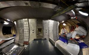
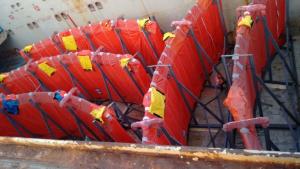
It takes 456 plasma-facing units, organized in twelve 30-degree sectors, to form the complete WEST divertor. In this picture, taken during last week's media visit, Jérôme Bucalossi introduces the sector that includes the six actively-cooled experimental monoblock assemblies procured by Japan and China. In the first phase of the WEST operational program, due to begin in the coming weeks, only six plasma-facing units arranged into actively-cooled assemblies of 35 monoblocks will be part of the divertor; the rest consists of non-actively cooled tungsten-covered graphite blocks just like in JET and ASDEX Upgrade tokamaks. ITER Japan has provided three of the assemblies and the Institute of Plasma Physics of the Chinese Academy of Sciences (ASIPP) the other three. This summer, eight additional plasma-facing units from Europe will be installed.   
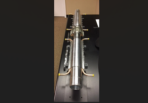
The six plasma-facing units from China and Japan, each made of 35 tungsten monoblocks, are clearly visible in this image. The other 29 are non-actively cooled tungsten-covered graphite blocks just like in the JET and ASDEX tokamaks. © Christophe Roux - CEA In this configuration WEST will produce plasma shots lasting only a few seconds. Shorts plasmas will preserve the life expectancy of the tungsten-covered graphite blocks, while allowing engineers to define the optimal geometry of the monoblock assemblies. In early 2019, when a complete actively-cooled tungsten divertor is installed, WEST will produce ITER-relevant plasmas of up to 1000 seconds. At that point the rejuvenated Tore Supra machine, which will celebrate the 30th anniversary of its commissioning in 2018, will fully enter into its role as a test bench and risk limiter for its giant neighbour ITER. (1) The neutrons from the fusion reaction in ITER will generate approximately 400 MW of power that do not participate in the heating of the plasma. Bearing no electric charge, the neutrons escape the magnetic cage and impact the inner wall, where their kinetic energy is transformed into heat. (2) One of WEST's missions will be to determine more precisely how, and over how large a surface, heat loads are deposited on the divertor's plasma-facing components. Read more about WEST here.
E_Box_delivery_1_small.jpg

Many will be heavier, none will be wider

Of all the components that will be delivered to ITER in the years to come, many will be heavier, taller and more spectacular than the two "E-Houses" that reached the worksite shortly after 1:00 a.m. on Thursday 9 February. But none will be wider: at 8.7 metres wide, the larger of the two E-houses was just 30 centimetres below the limit that the ITER Itinerary can accept...   The two "houses" had travelled together from China. Upon arrival at ITER, the larger E-house (27 metres long, 8.7 metres wide, 130 tonnes) was put in storage at the entrance of the ITER site until its concrete base could be realized; its near twin (24 metres long, 8.3 metres wide, 110 tonnes) was installed in its final location between the electrical switchyard and the large transformers.   The installed E-house will be progressively equipped with the complex set of cables that will connect it through the switchyard to the French national grid.
SPIDER_ISEPS_layout.jpg

Signatures complete transfer of ion source power supply

Occupying a full room at the PRIMA neutral beam test facility in Italy, the ion source extraction grid power supply is an important power supply component for the ion source test bed SPIDER. Following successful site acceptance tests last year, the equipment has now been officially transferred for use. In Padua, Italy, the neutral beam test facility for ITER—PRIMA—is taking shape. The physical infrastructure has been completed, components are being installed for the ion-source test stand SPIDER, and manufacturing is underway for the components of the injector test stand MITICA.   The goal of SPIDER is to develop a full-size ion source equivalent to that which will be used on the heating neutral beams and the diagnostic neutral beam at ITER.   The power required for the operation of SPIDER will be provided by an acceleration grid power supply provided by India and an ion source and extraction grid power supply (ISEPS) and transmission line provided by Europe in order to feed the radio frequency ion source. The design and manufacture of the power supplies were carried out in collaboration with the European Domestic Agency, PRIMA host Consorzio RFX and the ITER Organization.   On 6 February 2017, the ownership and responsibility for the first part, the ion source extraction power supply ISEPS, was transferred from the European Domestic Agency to the ITER Organization. As the test facility is located in Italy, the operation of ISEPS will be in the hands of Consorzio RFX; for this reason, the responsibility for use of the power supply was transferred on the same day to the RFX team.   The multi-year development of the ion source extraction grid power supply came to an end in 2016, with successful site acceptance tests at PRIMA. (Photo: April 2016) The signature process, which took place remotely, is the culmination of a number of key milestones: a final design review on the ion source and extraction power supply in May 2011; successful factory acceptance tests in May 2014; delivery to the PRIMA site in April 2015; successful site acceptance tests in April 2016; the completion of all site activities in September 2016; and finally the signature of the transfer forms on 1 February 2017.   The achievement of so many successive milestones was the result of close collaboration between the European Domestic Agency, the supplier OCEM ET (Italy) and its main subcontractor Himmelwerk GmbH (Germany), PRIMA host Consorzio RFX, and the ITER Organization.

Designing a valve as a confinement barrier

Fifty-six electron cyclotron waveguides will enter the Tokamak Building to deliver 20 MW of heating power to the ITER plasma. The challenge is that each one could act as a breach in building confinement during a catastrophic event such as an earthquake or fire. A special type of valve is under development with industry to improve confinement at each waveguide "point of entry."   The electron cyclotron heating system in ITER system heats the electrons in the plasma with high-intensity beams of electromagnetic radiation. The beams, produced by 24 powerful high-frequency (170 GHz) gyrotrons in the Radio Frequency Building, travel approximately 100 metres along transmission lines to the tokamak, where electron cyclotron launchers deliver them into the plasma.   The US Domestic Agency is responsible for 88 percent of the electron cyclotron transmission lines—including research and development, design, fabrication, and interfaces—while the ITER Organization is responsible for the installation of the transmission lines (12 percent).   The transmission lines feature multiple lines of aluminium waveguides with internal corrugations that can transmit up to 2 MWs per line for 3000 seconds, with a peak power density greater than 3 GW/m² at the centre. The transmission line has a circular cross section (ø63.5 mm) and has small grooves machined into its internal surface that minimize the power transfer losses to ≤ 10 percent.   Approximately 4 km of transmission lines will connect the 24 gyrotron sources in the Radio Frequency Building to 56 feeds with 10 types of waveguide components. The main interfaces include sources, launchers, buildings, port cells, water cooling, and auxiliary vacuum systems. There are 56 electron cyclotron waveguides entering into the Tokamak Building, and each could act as a breach in building confinement during a catastrophic event such as a large earthquake or fire.   To mitigate this risk a new valve is being developed to be installed at each "point of entry" of the waveguides—both in the Tokamak Building and the vacuum vessel port cells. The electron cyclotron teams at ITER and the US Domestic Agency are working with an outside contractor—the Swiss valve company VAT—to develop a new microwave component with the aim of improving the confinement of the waveguide penetrations.   The valve will not act as a vacuum barrier, but will form a confinement barrier limiting the flow of tritiated gas to <1mbar•litre/second from the galleries in the Tokamak Building to the Assembly Hall. There is limited space for these valves, as up to 24 waveguides are packed together in one penetration, so VAT has taken up the challenge of developing a new valve—the electron cyclotron isolation shutter valve. The shutter valve would swing a small plate into the gap of a waveguide to block, or isolate, its two sides.   The electron cyclotron teams at ITER and the US Domestic Agency are working with an outside contractor—the Swiss valve company VAT—to develop a new microwave component. Pictured, members of the team at VAT during a visit earlier this year. Prior to embarking on the design, the ITER Organization and the electron cyclotron team from the US Domestic Agency have been collecting the specific requirements on the valve during various load conditions (i.e., fire, earthquake, increases in torus pressure, coolant leaks ...) and characterizing the valve requirements for each event. The requirements are then reviewed with VAT to ensure that existing technology can be extrapolated to this new component.   The action plan is to develop a prototype design of the isolation shutter valve with a manufacturing process and test plan defined and reviewed by ITER safety experts prior to "cutting metal." Then, the prototype will undergo testing for microwave propagation, vacuum compatibility and, most importantly, safety functions. If the valve passes all these tests, then the prescribed manufacturing and testing process is validated and we can proceed toward the final design review.   Recently, members of the US and ITER teams visited VAT near Buchs, Switzerland to review the various requirements, agree on the steps toward the finalizing the design and producing the first prototype, and review the qualification procedures including welding, testing and related FEM* analysis.   An existing ITER Organization-VAT contract will be amended in early 2017, with the aim of reaching the first prototype tests within a year.   * Finite Element Method: a computer model that simulates a large object in small pieces (or elements) and permits the propagation of forces to be represented. 
Sammy_Daan.jpg

Fusion, explained by Sammy (13) and Daan (12)

The task was to make a film related to global warming and climate change. A challenge 12-year-old Daan and his 13-year-old classmate Sammy from the Coornhert High School in Gouda, Netherlands, were more than ready to take up.  "I had recently seen a video explaining the basics of fusion energy and thought this would be the perfect opportunity to learn more about it," Daan recalls. And so the story begins ..."We first did some basic research on the subject, though this was pretty difficult as most of the information we could find was in the form of either technical papers about fusion experiments or oversimplified models. When we discovered there wasn't a simple but yet realistic explanation about fusion energy we decided to base our video around that."So the "Coornhert fusion research team," as Daan and Sammy soon called themselves, developed a script, filmed some takes, recorded the audio (Daan recorded the English, Sammy the Dutch), and moved on to editing. "I think in total the editing, 3D modelling and motion tracking took me about 36 hours—mostly because halfway through rendering my hard drive crashed and I had to start all over again," Daan says. "But in the end it worked and we are very happy with the result." To see the result of the students' efforts, click for the English or Dutch versions. 
Of interest

1st segments of the cryostat lower cylinder en route

https://www.iter.org/of-interest?id=691
On 30 January, six large steel elements of the ITER cryostat left the port of Hazira, India for their one-month voyage to ITER. These are the first segments of the cryostat lower cylinder (tier 1). On site at ITER, assembly activities (welding, testing) for the cryostat base have been underway since September 2016  

Update available to 360° ITER site tour

https://www.iter.org/of-interest?id=690
A lot has happened on the construction platform since the ITER 360° virtual tour was released to the website last year with an October data set. The first ground-level walls of the Tokamak Complex are now visible from afar, the circular bioshield dominates in the centre, and two new buildings—one for radiofrequency heating and the other for cryogenics—are now completely framed out. Elsewhere on site, excavation and early foundation works are underway and the first activities to energize the 400 kV electrical switchyard have been carried out. The best way to catch up on recent progress is to open the January 2017 update of the 360° virtual tour. Click here or visit the homepage of the ITER website.
Press

Как построить солнце. Специальный репортаж Антона Борисова

http://www.vesti.ru/videos/show/vid/706897/

On a visité le réacteur nucléaire qui pourrait « mettre le Soleil en boîte »

http://www.01net.com/actualites/on-a-visite-le-reacteur-nucleaire-qui-pourrait-mettre-le-soleil-en-boite-1099078.html

Fusion nucléaire : en attendant ITER, voyage au cœur du tokamak West

https://www.industrie-techno.com/fusion-nucleaire-en-attendant-iter-voyage-au-c-ur-du-tokamak-west.48027

Hot topic: the future of fusion

http://www.neimagazine.com/features/featurehot-topic-the-future-of-fusion-5736033/

Lab24 - Energía de fusión (video 18:00)

http://www.rtve.es/alacarta/videos/lab24/lab24-energia-fusion-universo-detalle/3902712/

Projet ITER sur la fusion thermonucléaire : où en est on ?

http://www.notre-planete.info/actualites/4579-ITER-chantier-CLI-2016