Logo
You're currently reading the news digest published from 13 February 2017 to 20 February 2017.
Featured (5)
Of interest (2)
Press (4)
Featured
MIFI_2_small.jpg

The magnet lab next door

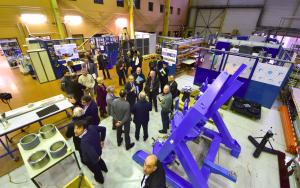
Two and a half years ago ITER and the French Alternative Energies and Atomic Energy Commission (CEA) entered a collaboration to prepare for the challenging task of commissioning and assembling the ITER magnets. A workshop-cum-laboratory, the Magnet Infrastructure Facilities for ITER (MIFI), was established on the "other side of the fence" from ITER, directly accessible by a rotogate, in a section of the large hall that hosts the fusion activities of CEA-Cadarache. Over an area of 700 m², four distinct labs are devoted each to a specific magnet-related issue or activity─a high voltage test lab, a low voltage test lab, a mechanical workshop including a large computer numerical control (CNC) machine, and an insulation/vacuum impregnation lab. Additional space is also made available for larger mockups. "What we do here is test the elements of the ITER magnetic system component by component," explains Bertrand Peluso, the MIFI technical coordinator on the CEA side. "The lab also enables us to assess in real conditions the technical teams that will be involved in the assembly phase and the procedures that will be implemented." CEA's experience in large superconducting magnets was acquired in building and operating the Tore Supra (now WEST) tokamak, whose construction was launched in the early 1980s, and more recently in providing, within the framework of the Broader Approach Agreement, half of the toroidal magnets to JT-60SA Japanese tokamak project . For close to a quarter century, the French public institution has also been involved in the R&D activities that led to ITER design and construction. And since the creation of MIFI in 2014, the lab has been the place where CEA experience is shared and where challenges large and small are faced in a collaborative fashion. "What's important here is proximity and flexibility," says Arnaud Devred, the deputy head of ITER's Magnet Division. "If an issue arises on a component being manufactured somewhere at the other end of the world, we can reproduce the fabrication process here—and sometimes the component itself—to determine where the problem lies. We've had issues pending for years which, thanks to the common work at MIFI, we were able to solve in a few weeks' time." Sample activities include: practicing the insertion of high-voltage cables for ITER magnet feeders on contorted cable duct mockups; fabricating busbar joint samples (similar to the ones which will have to be assembled in the tokamak pit) for testing in ITER-relevant conditions at the SULTAN facility in Switzerland; testing cables, plugs, and sensors under high voltage and cryogenic conditions ... in short, everything pertaining to critical magnet components and auxiliaries.   A large Computer Numerical Control (CNC) machine is part of the MIFI set of labs, along with a high voltage test lab, a low voltage test lab, and an insulation/vacuum impregnation lab. © Christophe ROUX - CEA Two-and-a-half years after its inception, MIFI is now preparing for a new phase dubbed "MIFI 2," in which the available space will be extended up to 2,000 square metres and, as machine assembly nears, mockups will be made available for assembly process qualification and training of technical staff.   "Most processes in ITER are first-of-a-kind," adds Arnaud. "Before getting into the real job, we need to check that processes are feasible and that staff is properly trained and certified."   Some of the equipment that will be at the heart of MIFI 2 operations is already in place. For example in one massive steel berth, a mockup of the toroidal field inner-outer intercoil structures will allow technicians to qualify the assembly procedures of these large steel "tabs" that will interconnect the 18 toroidal field coil cases before the real operation is carried out in the Assembly Hall or the Tokamak Pit.   The mockup is designed to simulate misalignments and to provide options to compensate them. With the help of a "zero-gravity arm" that augments an operator's movements and enables the handling and insertion of 300-kilo attachment studs, assembly technicians will train (and eventually be certified) for this highly delicate operation that must be performed with a precision of 10 microns.   "Over the last years MIFI has provided a great opportunity for newly recruited ITER engineers and technicians to get a hands-on experience of magnet issues," says Arnaud. "This practical experience is essential for an engineering project like ITER and will be pursued in the MIFI 2 phase, with an emphasis on assembly procedures."
Central_Solenoid_Group_small.jpg

First central solenoid module ready for heat treatment

In a major milestone, the US contractor responsible for the fabrication of the ITER central solenoid has successfully joined seven individual coil sections, or more than 6 kilometres of niobium-tin superconductor. Now, the module core will spend one month in heat treatment at temperatures of up to 650 °C. At the General Atomic Magnet Development Facility outside of San Diego, California, the ITER central solenoid team has something to celebrate. After spending months carefully winding the seven individual sections of the first central solenoid module, composed of over 100 tonnes of cable-in-conduit conductor, engineers and technicians have successfully completed the joining of the sections.   That makes the module ready for the next step—heat treatment—a month-long process during which the niobium-tin alloy becomes superconducting. The component will be placed in a furnace at temperatures of up to 650 °C, with constant temperature hold time exceeding 350 hours.   While the first module is in the heat treatment furnace, the team will begin work on joining the conductor sections of the second module. The central solenoid magnets is formed from six individual coil modules stacked vertically within a "cage" of supporting structures; General Atomics is also producing a seventh module as a spare.   Read the full press release here. 
Rroof_Laban_3b_small_cropped.jpg

Activity on every floor

At every floor of the Tokamak Complex—from the lowest underground level (B2) all the way to the second regular level of the bioshield (L2)—there is intense activity. Civil works at Tokamak Building basement levels B2 and B1 are now fully complete and finishing works have started. Just overhead, flush with the level of the construction platform, three out of the nine plots for the L1 basemat have been poured.At the centre of this photo taken last Thursday, as night descended, the first of 18 embedded plates are clearly visible. Anchored in the massive columns at L2 level, these 4.5-tonne plates will support the brackets of a temporary in-pit tool, necessary during the assembly of the vacuum vessel sectors. In one month, work is scheduled to start at the L3 level of the bioshield.Work is progressing rapidly on the less complex Diagnostics Building, to the right of the image, where civil works have been completed up to L1 level and reinforcement is underway for the L2 concrete slab. The B1-level walls of the Tritium Building, at the opposite end of the Tokamak Complex, are nearly complete and the installation of L1 formwork is imminent. Finally, the steel structure has been erected for the Radio Frequency Heating Building adjacent to the Assembly Hall. Two concrete slabs are planned to create the three storeys of the building.
Research_Plan_Workshop_2_small.jpg

Bringing the Research Plan up to date

The ITER Research Plan is an ITER baseline document which outlines the main lines of science and technology research derived from the project's mission goals. It was initially developed during the ITER Design Review in 2007-2008 in order to analyze the experimental program towards high-fusion-gain deuterium-tritium operation. It was further elaborated in subsequent years to identify the main lines of physics R&D required to support the preparations for ITER operation, as well as to incorporate the main elements of the testing program for the test blanket modules (TBMs), which will provide the first tests of tritium breeding technology in the fusion environment.   Eventually, the ITER Research Plan will be expanded to encompass all of the science and technology research required to meet ITER's overall goal of demonstrating the scientific and technical feasibility of exploiting magnetic confinement fusion for the production of energy for peaceful purposes.   With the acceptance of the revised ITER baseline cost (ad referendum) and schedule by the ITER Council in November 2016, a study has been launched to bring major elements of the Research Plan up to date and to adapt the overall plan to the framework of the staged approach.   In the staged approach to assembling ITER, assembly phases will alternate with periods of operation as a way to minimize risk.   A preliminary workshop was held in July 2016 involving fusion science experts from the ITER Member communities and ITER Organization/Domestic Agency staff. The result was an initial analysis of the Research Plan within the staged approach.   Last week, many of the same experts met at the ITER Organization's Headquarters to develop the Research Plan in greater detail and to integrate an updated analysis of the TBM testing program. About 25 leading physics experts from the Domestic Agencies and the Members' fusion research centres and universities joined experts from the ITER Organization in a four-day workshop which analyzed the phases of ITER experimental operation leading to long-pulse, high fusion power production. Experts from ITER and the Members' test blanket module teams worked in parallel to adapt the test blanket module testing program to the staged approach.   The output from these activities will now be integrated into an overall framework for the revised Research Plan, and the scientists and engineers will get together again in March to begin drafting the updated document, which will form the basis for research and operations planning in the coming years as preparations towards First Plasma gather momentum.
PF_6_small.jpg

Further validation for ring magnet fabrication

Once a component mockup has been produced—and before fabrication can begin on the actual component or system—a manufacturing readiness review is required to ensure that materials, tools and procedures meet the approbation of the ITER Organization. Recently, separated by only a few weeks, manufacturing readiness reviews were held on opposite sides of the globe for poloidal field coil dummy double pancakes—in China for poloidal field coil # 6 (PF6) and in southern France at ITER for poloidal field coil #5 (PF5).   PF6—the second smallest of the ring-shaped magnets that circle the ITER Tokamak (Ø 10 metres)—will be manufactured at the Institute of Plasma Physics of the Chinese Academy of Science, ASIPP, in Hefei for the account of the European Domestic Agency; nearly twice as large, PF5 (Ø 17 metres) will be manufactured directly by Europe in the Poloidal Field Coils Winding Facility on the ITER site.   On opposite side of the globe, PF5—with a diameter nearly twice as large as that of PF6—will be manufactured directly by Europe in the Poloidal Field Coils Winding Facility on the ITER site. Poloidal field coils are made of spiralled coils of conductor called double pancakes, stacked together and hardened into a rigid assembly by way of resin impregnation. PF6 will be made from nine such double pancakes, while PF5 will be formed from a stack of eight. In order to realize full, two-layer dummy mockups, two 718-metre unit lengths were used for PF6 and two 737-metre unit lengths for PF5.   As part of the qualification of the winding tooling and processes, these mockup pancake windings were validated by manufacturing readiness reviews earlier this year, giving the green light for the start of real double pancake winding for both poloidal field coils.   In a similar manner, the next stage—vacuum impregnation—will be reviewed once the impregnation operations have been completed on the mockups and verified, opening the way for this step to be carried out on the production double pancake windings.
Of interest

Quench tank delivery video

https://www.iter.org/of-interest?id=693
Some 4,500 components, large and small, will be shipped to ITER for integration into the ITER cryoplant, which is under construction now on the ITER platform. Two of the largest were delivered in November 2016 by the European Domestic Agency: 35-metre quench tanks that will store gaseous helium in the case of a magnet quench. The tanks are formed from an inner stainless steel container that will hold the gas and an outer carbon steel shell that will insulate the inner vessel and keep the temperatures low. Manufacturered by Air Liquide subcontractor Chart Ferox (Czech Republic) according to ITER Organization and European Domestic Agency requirements, the tanks travelled at night in a long convoy along the ITER Itinerary from the Mediterranean port of Fos-sur-Mer to ITER. See the full report here (including a 4'10" video).

A new code and its photographic by-product

https://www.iter.org/of-interest?id=692
A physicist at the Culham Centre for Fusion Energy (CCFE) is developing a code to calibrate camera views of fusion experiments.   For the past two years, Scott Silburn has been leading the development of Calcam, a program for calibrating camera viewing geometry on fusion devices. The program allows the user to match up features seen in the camera images with those on a computer-aided design model from the drawing office at Culham. From this, the position, orientation, and lens properties of a camera system can be determined. This information can then be used to calculate exactly where the camera's lines-of-sight pass through the plasma, and also which locations on in-vessel components correspond to which positions in the image. An example application of the code is improved positional calibration for JET's high-resolution divertor infrared cameras, which measure the heat loads at the strike points where the plasma interacts with the divertor tiles. The improved information has been used to improve the accuracy of some of the signals from the cameras, and makes it easier to compare the camera data against other diagnostic signals. An agreable off-shoot of the technique is that it produces interesting images, as seen in the image above (photo credit: CCFE). Read the original story here.
Press

Five technologies that will change how we live

https://www.ft.com/content/1bf4cdc8-f251-11e6-95ee-f14e55513608

Is Fusion Energy in Our Future?

https://www.scientificamerican.com/article/is-fusion-energy-in-our-future/

Method for designing fusion experiments improved

http://www.chemeurope.com/en/news/161862/method-for-designing-fusion-experiments-improved.html

A Cadarache, des tests décisifs pour la fusion nucléaire

http://www.lemonde.fr/sciences/article/2017/02/13/a-cadarache-des-tests-decisifs-pour-la-fusion-nucleaire_5079006_1650684.html