you're currently reading the news digest published from 05 Oct 2020 to 20 Oct 2020
featured7
press17
featured
Cooperation | Canada returns to the table
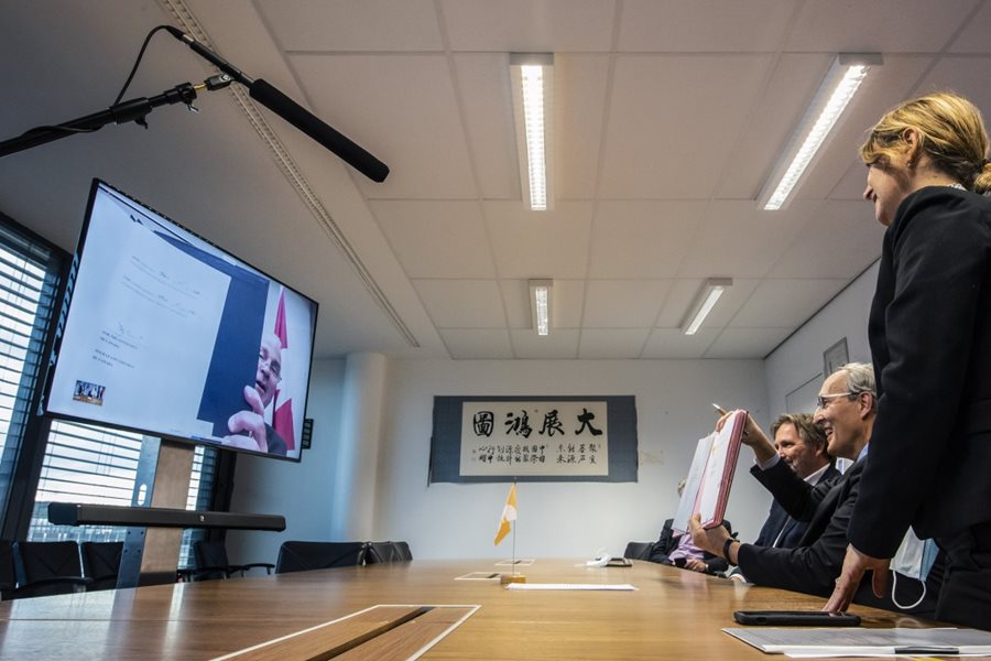
Canada, one of the early participants in ITER, is back in the project. On Thursday 15 October, Bernard Bigot, on behalf of the ITER Organization, and Assistant Deputy Minister Dan Costello, on behalf of the Canadian government, signed a Cooperation Agreement. The agreement sets out the terms of cooperation for the transfer of Canadian-supplied nuclear material (tritium), and tritium-related equipment and technology. Canada played an important role in the early years of ITER . In the spring of 2001, as the ITER Members¹ were finalizing the blueprint of the installation, a group of businesses, academics and trade unions offered to build ITER on Canadian soil—a proposal that provided a much-needed international credibility to the project. Although the Members eventually made a different choice, contacts between ITER and Canada were never severed. The country's expertise, especially in tritium-related technologies, made it a natural partner for ITER and, as Director-General Bernard Bigot emphasized prior to this month's signature, 'it was becoming evident that cooperation between the Canadian Government and the ITER Organization should be developed.' In April 2018, the two parties signed a Memorandum of Understanding agreeing to explore the possibility of future cooperation and, since then, several Canadian government representatives have visited the ITER site. ITER will begin producing deuterium/tritium plasmas in the mid-2030s. Over the course of its experimental campaign, it will consume the totality of the world tritium inventory, which amounts to only a few dozen kilos. The main source of tritium, which occurs naturally only in trace amounts, is a type of fission reactor called the CANDU. Developed in Canada in the 1950s and 1960s, CANDU reactors use natural uranium as fuel and heavy water as moderator, generating small quantities of tritium as a by-product. There are presently 31 CANDU reactors operating around the world, 19 of them in Canada. Beyond direct cooperation with Canada, the Cooperation Agreement signed on 15 October is indispensable to allow for the 'retransfer' of technologies from countries such as Korea or Romania, both partners in ITER, who also operate CANDU reactors. The establishment of this Cooperation Agreement with the Government of Canada will enable the ITER Project to associate one of the largest and most experienced technically-relevant tritium communities outside of the founding ITER Members. ¹Because the United States left the ITER Project between December 1998 and January 2003, and Members China, Korea and India had not yet joined, in 2001 the ITER Members were Europe, Russia and Japan.
In-vessel coils | First components arrive on site
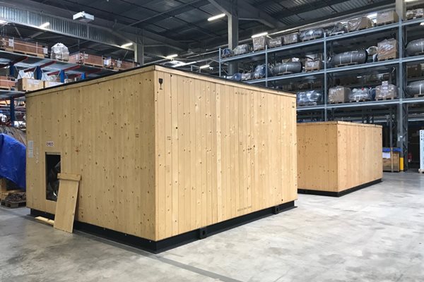
ITER has received the first shipments of mineral-insulated conductor for ITER's in-vessel coils. The first lengths are destined for winding and bending trials as well as for the production of the first vertical stability coils on site. Produced by the Italian consortium ICAS S.r.l., the first four conductor lengths—each 105 metres long, on spools—have been transferred to a special temperature and humidity-controlled storage area on site. Another two sets of straight conductor lengths (20 units, each 12 metres long) have been delivered to ITER contractor Vitzrotech, in South Korea, for the qualification and manufacturing of an auxiliary component called in-vessel coil feedthroughs. Coming after nearly a decade of development and a detailed qualification phase to confirm the manufacturability of the final design, these deliveries represent a major milestone in the ITER in-vessel coil program. The mineral-insulated conductor has been specially developed for the in-vessel coils to withstand large transient electromagnetic fields, high radiation flux, and high temperature. The mineral layer—made of compressed magnesium oxide (MgO) powder—has three main functions: structural support of the copper conductor; thermal conduction between the stainless steel jacket and the copper conductor; and electrical insulation between the jacket and the conductor. The specific hydroscopic nature of this layer—as well as the final high stiffness of the conductor—must be taken into account in the development of winding and bending procedures for both types of in-vessel coils (vertical stability and ELM). Two ring-shaped vertical stability coils will be mounted on rails close to the plasma—but behind the protection of the blanket modules—in order to provide a fast and efficient contribution to plasma control. Located at the top and bottom of the vessel, the coils differ slightly in diameter, but are built from the same type of mineral-insulated conductor. Both coils are wound from four turns of conductor that are connected in series. The length of one turn varies: an upper vertical stability coil turn is roughly 35 metres; a lower vertical stability coil turn is about 47 metres, without feeders. As part of risk reduction related to the insulation performance of the in-vessel coil conductors, an irradiation program has been developed and will be performed at Oak Ridge National Laboratory (US). An essential part of this program is to measure the breakdown voltage and resistance as a function of cumulated gamma irradiation dose. Another challenge ahead is the manufacturing of in-vessel coil feedthroughs—ancillary components that are part of the feeders that deliver electrical power and cooling water to the coils, and which have particular requirements because they cross between the vacuum boundary and normal atmosphere. Feedthroughs are classified as protection- and safety-important components and, as such, have stringent requirements in terms of reliability, inspection, and capability to withstand accidental events such as plasma disruptions, seismic events, and power supply failures without the loss of their safety function. Bending and winding trials for the vertical stability coils will start in 2021, as soon as the tender process is completed and the contract is awarded. The qualification of the feedthroughs will conclude by end of 2021, and the first batch of feedthroughs is expected in September 2022. Conductor manufacturing should continue through early 2023, when the last conductor lengths are delivered to the supplier of the ELM coils. *The ICAS consortium is composed of ENEA, Frascati, Italy (general project management, scheduling, administration and quality assurance); Tratos Cavi S.p.A., Pieve Santo Stefano, Italy (cable manufacturing); and Criotec Impianti S.r.l., Chivasso, Italy (jacketing and the completion of the unit conductor lengths).
Controlling divertor power fluxes in 3D | ITER Scientist Fellows make progress
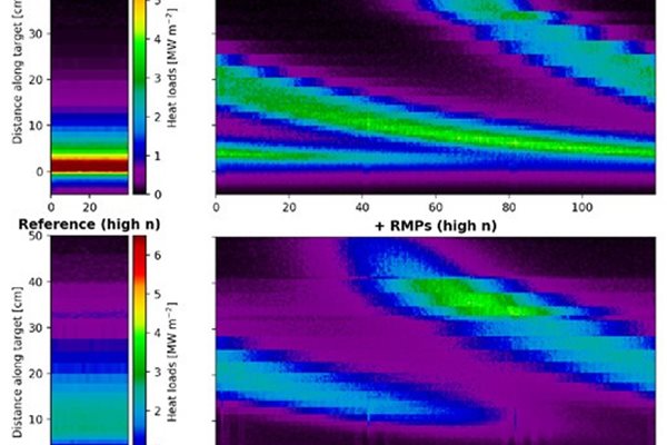
New research results open a path to an integrated solution for optimizing the control of stationary and transient power fluxes on ITER. Tokamak plasmas are basically symmetric toroidally—and so are the power loads to the divertor. Power fluxes change with distance along the divertor targets when looking at the cross section of the torus but not in the toroidal direction (Figure 1). In ITER, these power fluxes are deposited in a very small fraction of the divertor area, so their magnitude can be very large for high-performance plasmas (high Q or fusion gain). Indeed, evaluations from both edge plasma modelling and empirical extrapolations show that, in the absence of mitigation measures, divertor power fluxes can exceed the design guidelines for the ITER divertor plasma-facing components (10 MWm-2) for high Q plasmas. To reduce these power fluxes, impurities are purposely injected in the divertor plasma to enhance losses by electromagnetic radiation (i.e., the emission of light). This spreads the plasma power flowing down to the divertor over a larger area, thus reducing the local power fluxes to below 10 MWm-2. This so-called semi-detached radiating divertor regime, on which ITER high Q operation is based, is routinely demonstrated in operating fusion experiments. However, the need to limit power fluxes in ITER goes beyond that of present experiments. In addition to the stationary power fluxes described above, ITER also needs to control transient power fluxes associated with high confinement plasmas (so-called H-modes) that are required for the achievement of high Q. The specific transients associated with H-mode plasmas are called ELMs (Edge Localized Modes). ELMs cause small losses of plasma energy, but on very short timescales (tenths of milliseconds). In ITER, because of the large plasma energy required to produce fusion power, the associated power fluxes can heavily erode the divertor target, reducing its operational lifetime to unacceptable values. ELMs need to be mitigated or, even better, eliminated. To achieve this transient power load control, ITER is equipped with a set of 27 in-vessel ELM control coils. By applying electrical currents in these coils, it is possible to modify the edge magnetic field and mitigate or eliminate the ELMs altogether. An unavoidable consequence of this technique, however, is that the edge plasma is no longer toroidally symmetric and thus has a full 3D structure (Figure 2). This can affect the radiative divertor solution which relies on a 2D plasma assumption. It is therefore necessary to confirm that the 2D stationary and 3D transient power flux control methods, impurity injection, and ELM control coils, can be compatible for the operation of high performance ITER plasmas. Initial experiments in EAST, which used currents at the plasma edge driven by radiofrequency waves to create a 3D structure, showed that indeed 3D edge magnetic fields deeply affect the access to radiative divertor conditions as the plasma density is increased. Near the intersection of the plasma with the divertor target, the power flux decreased with increasing density—similar to the 2D situation. However, far from this intersection, where the plasma power fluxes are non-toroidally symmetric, the power fluxes increased with increasing density. Following this initial finding, tokamak experiments equipped with ITER-like ELM control coils have studied this issue in further detail (ASDEX Upgrade, DIII-D, EAST, KSTAR, NSTX). Unfortunately, it has not been possible to reproduce the divertor and main plasma conditions that are expected in ITER simultaneously. When the 3D divertor plasma is dense and cold and radiates the plasma power away, as required in ITER, the main plasma is also dense and cool—making the 3D edge magnetic field structure differ from that in ITER and vice-versa. This has prevented the direct extrapolation of present experimental results to ITER and has made another approach to solving the conundrum necessary. This issue was put to the ITER Scientist Fellows—a group of leading plasma modelling experts from the ITER Members supported by their national fusion programs (the US Department of Energy and EUROfusion in this case) and the ITER Organization—and they rose to the challenge. Through the effort of Scientist Fellow specialists in 3D edge plasmas (H. Frerichs, O. Schmitz, and D. Reiter), 3D magnetic fields (Y. Liu), and their collaborators—and coordinated by staff from the ITER Organization Science Division (X. Bonnin, R. A. Pitts, and A. Loarte)—a first understanding of power flux control in ITER's 3D plasmas has emerged. The results, recently published in Physical Review Letters, show that the qualitative behaviour initially observed in EAST will be reproduced in ITER plasmas, and that this is due to the specific 3D structure of the edge magnetic field that the ELM control coils will create in ITER plasmas (Figure 1, right side). This understanding provides a way to optimize the control of stationary and transient power fluxes by tuning the 3D edge magnetic fields applied for ELM control in ITER. The ITER ELM control coils have recently concluded their final design review and are capable of providing a wide range of 3D magnetic field structures, including the possibility to rotate them during ITER plasma discharges to allow optimization. The ITER Scientist Fellows and their collaborators had previously studied the optimization of the applied 3D fields for ELM control alone. The new results, achieved through joint effort, open the path to include the divertor plasma in the optimization process to provide an integrated solution for ITER to control the divertor power fluxes. H. Frerichs, O. Schmitz, X. Bonnin, A. Loarte, Y. Feng, L. Li, Y. Q. Liu, and D. Reiter. 'Detachment in Fusion Plasmas with Symmetry Breaking Magnetic Perturbation Fields.' Physical Review Letters 125, 155001 (9 October 2020). https://doi.org/10.1103/PhysRevLett.125.155001.
Heat rejection basins | A massive fill-up
When the ITER Tokamak begins producing burning plasmas and auxiliary systems are operating at full capacity, the amount of heat to be removed from the installation will be in the range of 1100 MW. The extraction and dissipation of such a huge amount of energy requires an oversize heat rejection system that comprises kilometres of piping, dozens of extremely powerful pumps, countless valves and filtres, massive cooling towers, and two water basins (one 'hot' and one 'cold') equivalent in size to six or seven Olympic pools. One of the basic requirements for any water basin is to be as leak-tight as possible. Although some loss of water through seepage is inevitable in concrete basins such as ITER's, an 'assessment of tightness' was decided prior to turning over the heat rejection system to the ITER commissioning team. On 14 October, the weeklong operation began. The gate that connects the basins to the nearby Canal de Provence was opened and water rushed in at the rate of 300 cubic metres per hour. Like a crane that needs to be tested at 110 or 120 percent of its nominal lifting capacity, the basins of the heat rejection system were 'overfilled' with 27,000 cubic metres of water, or 7,000 m³ more than their operational volume. The basin walls and floor are thick and sturdy, but the pressure that is exerted by 27,000 tonnes of water is enormous. Topographic targets installed at several locations on the basin structures are monitoring 'settling,' which is expected to be in the range of 0.5 centimetres. Once the basins are filled and stabilized, the water level will be closely observed by a set of radars and the measurements compared to 'witness tanks' to account for evaporation. If radars register a drop beyond the acceptable leak rate (on the order of a few cubic metres per day due to the porosity of the concrete, the occasional micro-fissures, and seepage through junctions), that would signal a problem. Five days into the test, all parameters are nominal. Water levels in the basins are rising at the rate of one metre per day; fill-up should be complete by the end of this week.
Fusion world | Teaching teachers about fusion
The possibility to visit three fusion facilities, all in one afternoon. Welcome to the new virtual world! More than 300 science teachers recently seized the opportunity and joined the first European Fusion Teacher Day, organized by the European Fusion Education Network FuseNet. Twenty-four institutions and universities from 16 countries across Europe acted as hosts to the first Fusion Teacher Day event (see the full list). Teachers could sign up to 17 parallel sessions given in 16 languages, and they did—eager to learn more about the current state of research and to directly exchange with the experts on topics such as possible environmental risks, the economic viability of fusion, and how students can enter the field. All questions were answered online by an international team of scientists and engineers. 'The success of fusion requires the next generation of scientists, policymakers, financiers and elected officials, among others, to have a grasp of the principles of fusion energy and to be able to debate the issues in an informed way,' explains Roddy Vann, FuseNet Chairman and Professor at York University (UK). 'Teachers, particularly in secondary schools, are critical in encouraging young people that they have a role to play. It was our great pleasure to host such a large number of educators at this inaugural teacher's day." After the sessions, the registrants were taken by livestream to the sites of three fusion experiments in Europe—the Golem tokamak operated by the Czech Technical University of Prague, where they witnessed a plasma discharge; the JET tokamak (UK), for a virtual tour and a stop in the control room; and finally a live feed from the ITER Assembly Hall. Educational material prepared for the event will be made freely available on the FuseNet website shortly. See more here.
Thermal shield | The ultimate heat barrier
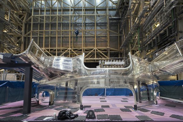
In the Assembly Hall environment, all yellowish hues and dull-grey structures, a strange component shines like a freshly polished mirror. Lying horizontal, it looks like a giant's tiara; when upended to the vertical position and paired to its missing half, it will fit a vacuum vessel sector almost like a glove. Sitting alone in a protected enclosure, the shiny component is the outboard segment of one of the nine vacuum vessel thermal shield sectors that, once assembled, will fit between the vacuum vessel and magnetic system of the machine and act as a barrier against the transfer of heat to the ultra-cold superconducting coils. The component's shine is due to the thin layer of silver that covers its entire surface. A 'low emissivity' material, silver raises an obstacle against the thermal radiation, in the form of electromagnetic waves, that a heat source generates. Radiation is one of the three ways heat can pass from one body to another, along with convection (through a fluid such as air) and conduction (by contact). The plating of the vacuum vessel thermal shield was done in electrolysis baths that required 5 tonnes of pure silver. Approximately 800 kilos went into the coating of the 2,000 square metres of vacuum vessel thermal shield—the equivalent of 100,000 sterling silver rings. The ITER superconducting magnetic system, which operates at the ultra cold temperature of 4 K (minus 269 °C), is protected from heat convection by the cryostat—the vast vacuum chamber that encloses the machine (no air ... no convection). It is insulated from warmer bodies—and everything is warmer than 4 K—by sitting on actively cooled pedestals, called gravity supports. 'Opaque' to electromagnetic radiation and positioned in the immediate vicinity of the magnetic system, the silver-coated vacuum vessel thermal shield, actively-cooled by gaseous helium at 80 K (minus 193 °C), adds a third and final protection against heat transfer to the ultra-cold superconducting coils. Not far from the enclosure of the giant's tiara in the Assembly Hall, another set of silver-plated elements is being arranged in a circle prior to being bolted together and inserted into the assembly pit. These soberly rectangular panels will form the lower section of the cryostat thermal shield that will stand between the cryostat inner wall and the magnets. Like the vacuum vessel thermal shield, the cryostat thermal shield (both procured by Korea) will contribute to protecting and insulating the uniquely frigid environment of the magnetic system—colder than the coldest winter day on Pluto.
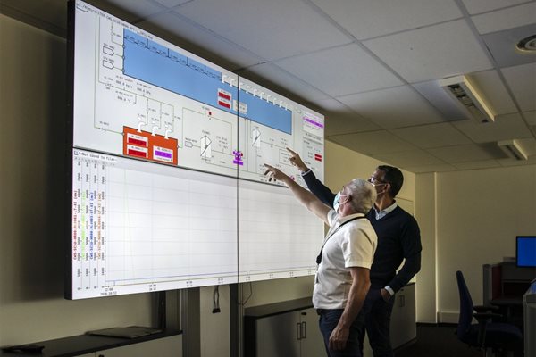
ITER's New Normal | Learning from the COVID-19 experience

The onset and persistence of the COVID-19 pandemic has altered behaviours in every societal sector. At ITER, the complexity of the project and the involvement of 35 countries on three continents compelled the rapid formation of a continuity plan, designed to prioritize critical activities. It also provided opportunities for ITER partners to learn from each other, and—perhaps ironically—to also learn from the positive aspects of new ways of working, initially forced by the coronavirus. This, in turn, has shaped a 'New Normal' at the ITER Organization. Over the past five years, ITER has built a culture of risk and opportunity management, in which challenges are evaluated in terms of both their potential negative impacts and what positive lessons can be learned, and the embedded opportunity that may lie hidden within any challenge. This culture shaped ITER's response to the challenges of the novel coronavirus. Clearly, COVID-19 forced multiple new ways of working: not only the social distancing, frequent handwashing, and facemasks that have become ubiquitous in 2020, but also the evaluation of each position—staff and contractor—among the 4,500 individuals who normally work at the ITER site. Whose presence is essential, and when? Which functions can maintain productivity while teleworking? What are the consequences, good and bad, of forcing more digitalization—paperless approvals, online meetings, remote collaborations? Not long after the 16 March lockdown across France, many at ITER began to notice the unanticipated benefits of the lockdown: less time spent commuting; greater capacity to multitask; more reliance on electronic processes; and, for many functions, a net increase, rather than a drop-off, in productivity. Staff-wide surveys confirmed these results. Director-General Bernard Bigot asked for a team to be set up, led by Chief Strategist Takayoshi Omae, to review the data, consider more innovation, and develop a forward-thinking plan to incorporate the lessons learned into a longer-term approach that would endure beyond the pandemic: a 'New Normal' for the ITER workplace. On 1 October, following a two-month trial period marked by more surveys and analysis, the ITER New Normal was officially launched. ITER Organization staff now telework up to three days per week, based on the mutual assessment of the individual and the line manager to optimize the work outcome. Flexibility is built in to accommodate job functions ranging from accounting and recruitment to oversight of construction and assembly. Online meetings and digitalized signatures and processes are becoming the standard, rather than the backup approach. A weekly ITER Bulletin keeps everyone informed of news and progress; in fact, many staff members say they feel more connected and better informed than in pre-COVID times. The pace of ITER assembly remains as intense and focused as always. But the New Normal has brought unexpected benefits, extending to environmental friendliness and improved quality of life. To sum up, less paper and petrol, equal or better productivity, and a smarter workplace.