you're currently reading the news digest published from 28 Feb 2022 to 07 Mar 2022
featured2
of-interest1
video1
press11
featured
Superconducting joints | Making ends meet
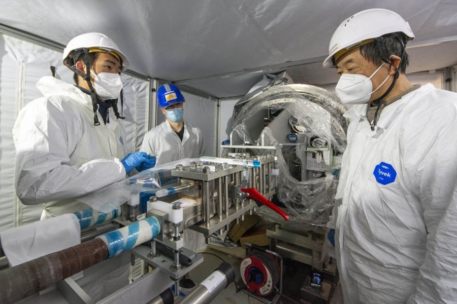
The one-million-component ITER machine is far more complex than a space probe, a deep-sea submarine or a Mars rover. In order to fulfil its operational objectives it relies on the optimal performance of innumerable interdependent systems and devices, most of which, fortunately, can be tested prior to integration and commissioning. In a few cases however, such testing is impossible and responsible officers are faced with a daunting challenge: how to make sure that an untested component will perform as expected once the machine is up and running? Answering this question is especially critical when it comes to assembling the superconducting joints that connect the high current feeding lines (busbar) to the magnets through the magnet feeders. Approximately 300 superconducting feeder joints need to be created as part of assembling the feeders, which are delivered in three segments to the ITER site. The joints need to be assembled in situ, once all the magnet feeder's elements are in place. What is expected from the joints is to oppose as little resistance to the current flow as possible: in theory, they should be as superconducting as the rest of the network that delivers up to 70 kA of electrical current to the magnets. In reality, what is needed is to limit the heating that would result from electrical resistance. The solutions that were developed (see box) bring the electrical resistance to an extremely low value—in the nano-ohm (nΩ) range. Despite this small amount of resistance and resulting small amount of heat generated, the joints can still be called 'superconducting.' However, once in place and assembled, a joint's electrical performance can only truly be put to the test at the ITER operating temperature (4 K, or minus 269 °C) and high-current (up to 70 kA), which will only be reached when the machine is commissioned. Detecting a problem at this stage, however, would lead to loss of time for repairs—a situation the team is determined to avoid by developing qualification programs for the technicians who will realize joint assembly and establishing precise procedure controls and step-by-step acceptance tests on samples and mockups produced throughout the qualification program to demonstrate technician skill. Over the past decade, different ITER Domestic Agencies have engaged in the development of the feeder component that fell within their scope. As far as feeder joints are concerned, the Institute of Plasma Physics of the Chinese Academy of Sciences (ASIPP) has been on the front line of research and development. With the close support of the ITER Organization feeder team and feedback from the ITER-CEA MIFI laboratory, ASIPP produced and qualified the first feeder joint sample in 2016. Qualification tests were performed in the Swiss facility SULTAN—the only installation in the world capable of imitating, within a significant magnetic field, the current intensity and temperature of ITER operational conditions. In that punishing environment the performance of the joints was confirmed. As machine assembly is progressing on the ITER site, the time has now come to prepare for the actual implementation of the joints. A multiyear training program has already qualified several specialists from the TAC1 assembly teams. New samples, similar to those realized during the qualification stage, were produced and again successfully tested in the SULTAN facility. It is of paramount importance that the qualified specialists maintain a stable and verifiable level of performance throughout the four years that joint assembly operations will last. In this perspective, and within the framework of the Site Support Agreement, the ITER Organization and the French Alternative Energies and Atomic Energy Commission (CEA) have recently built an installation called SELFIE (for 'self-field') that will test the production proof samples that every qualified specialist will be required to produce. Located at CEA-Cadarache on the other side of the ITER fence, SELFIE can be described as a small, close-to-home SULTAN. The main difference between the two facilities is that SELFIE is operating without an external magnetic field whereas SULTAN is equipped with a magnet that delivers a very strong field (4 tesla). In SELFIE the magnetic field is self-generated by the electrical current in the sample—hence the installation's name. The SELFIE installation is encased in a 6.2-metre-tall, 0.86-metre-in-diameter cryostat hosting a thermal shield and a tank filled with liquid helium at 4 K. The helium inner tank accommodates both the superconducting transformer that delivers the 70kA current and the 3.60-metre-tall 'sample' to be tested. The conditions to which the samples will be submitted in SELFIE are similar to those the actual joints will face in the ITER coil termination boxes. The only parameter missing is the background magnetic field, but its influence is not essential to checking the baseline resistance value. As actual joint assembly operations progress, the qualified specialists will be required to produce test samples every six months in order to verify that their performance remains at top level—an ingenious and efficient way of 'testing' what cannot be tested.
Diagnostics | A fast new way to see inside the vacuum vessel
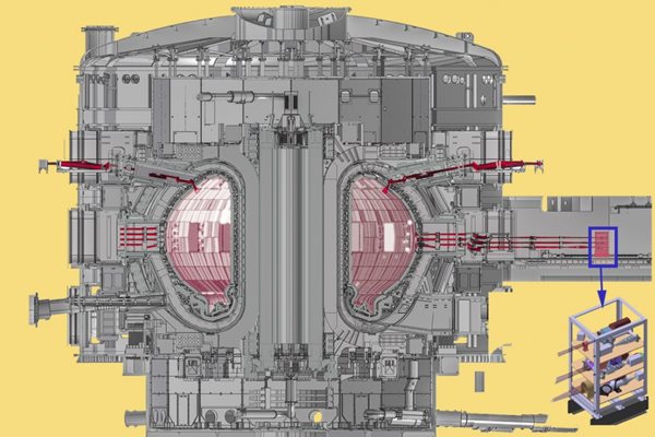
A new system, called the 'in-vessel lighting system,' will make it easier for ITER operators to quickly assess potential damage to the inner wall by shining visible light into the vacuum vessel and taking pictures. Just a few centimetres away from the hot plasma in ITER is the blanket first wall, which is made of beryllium. Although designed to handle high heat flux, the wall can be locally damaged if the plasma leans on it incorrectly. Proceeding to the next pulse without first checking for issues could be costly. The plasma lean could reoccur in a subsequent pulse, leading to further damage. Thanks to a large suite of diagnostics that measure the temperature of the wall during a pulse, operators can easily tell when something overheats. However, the sensors will not give them enough information about the extent of potential first wall damage. When in doubt, operators can use a powerful diagnostic called the 'in-vessel viewing system,' which has big arms that are moved into the plasma chamber to scan the surface and measure surface topology. But that system takes a long time to deploy and run—using precious time when the reactor might otherwise be used to run experiments. 'The in-vessel viewing system is very powerful, but it isn't meant for quick and frequent checks,' says Martin Kocan, Diagnostics Coordinating Scientist in the Ex-Vessel Diagnostics Section. 'We need to give the operators a mechanism to look inside after any given pulse—and that could amount to many thousands of times throughout the lifetime of the project. The existing system was not designed to be deployed so many times.' A clever design uses existing equipment As a result, the ITER diagnostics team did a conceptual design for a new system, the in-vessel lighting system, that is a little cruder, but that can be deployed quickly and often. 'The new system piggybacks on an existing system, called the 'wide angle visible and infrared system,' which uses infrared cameras to take measurements of the wall temperature during a pulse. By building on top of what already exists, we've found a more cost-effective solution than if we built it from scratch,' says Martin. The wide angle visible and infrared system takes the light from the plasma, channels it through mirrors and lenses, and sends it through 20 different optical channels to cameras. The in-vessel lighting system will add light into the chamber by sending it along the same paths, but in reverse. The light travelling through the optical fibres will come from lasers, placed far from the plasma. Each optical path will be equipped with a dedicated camera to capture images of the inside of the tokamak with high spatial resolution. 'We have 20 such views in total looking all around the tokamak routinely during a discharge so we can monitor most of the plasma-facing components,' says Martin. 'The in-vessel lighting system will use 19 of the 20 views to inject the light for illumination, and the remaining view to take the picture with the dedicated camera.' The new system is versatile—each view can be used to either inject light or to take an image. So at any given time, the camera from any of the views can be used. 'It still takes about 30 seconds to take each picture, because even with the 19 light sources, the illumination won't be anywhere close to the intensity you get when taking a daylight image. We will inject only about 19 W of light inside the torus. But every 30 seconds, we can change the configuration and start taking a view from different angle.' The new system covers 80 to 90 percent of the surface area within 10 minutes The spatial resolution of the images depends on the distance from the camera to the object, but it will be on the order of a few millimetres, which is enough to detail potential wall damage such as melt features. Some of the views overlap and software can be used to combine the overlapped images to get more detail. When the views are alternated and a picture is taken from each of the optical paths, the operation produces up to 20 full images of the torus wall. 'We expect to be able to cover about 80 to 90 percent of the vessel surface,' says Martin. 'That means there will still be areas we can't see at all—and of course there's a risk a melt will occur in one of those blind spots. But the views are dictated by where we can place the cameras.' The new in-vessel lighting system is fast and gives a first indication about the location and extent of any damage. It allows operators to determine within a couple of minutes whether they can safely go on with the next plasma discharge or whether the more complex system needs to be deployed to examine the first wall in more detail. Starting from this year the team will take the conceptual design and develop it further. They are now preparing for the tender process to find a partner to do the detailed design that will ultimately be used by a manufacturer. In parallel, the team is working on securing interfaces for the system—space allocated in the ports, and provisions for electrical services and cooling water for the cameras.
of-interest
Bécoulet's "Star Power": Fusion made simple and inspiring
A theoretical physicist, but one who views theory as something 'to be put to use," Alain Bécoulet can speak (and write) about fusion in terms that are both simple and inspiring. In his recently published Star Power: ITER and the International Quest for Fusion Energy (MIT Press), he offers a concise and accessible overview of fusion energy promises and challenges, not only explaining the underlying science and technology but also describing the massive international effort to harness this potential new energy source. Having embraced plasma physics in the mid-1980s as a student at France's prestigious École Normale Supérieure, Bécoulet draws from his long experience in fusion research, first at France's Institute for Magnetic Fusion Research (IRFM), and since February 2020 as head of the ITER Engineering Domain, to explain how the long-pursued dream of harnessing the energy of the Sun and stars is on the verge of becoming reality. Find out more here.
video
The ITER Research Plan, How to Reach Q=10