Reaching target position is a 5-day operation
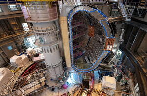
Each of the nine sector modules that form ITER’s plasma chamber is approximately 13 metres tall and, once rid of its lifting rig, weighs in excess of 1,200 tonnes. In terms of height, this is the equivalent of a five-storey building; in terms of load, each module weighs nearly as much as three fully loaded Airbus A380s or Boeing 747s. Once lifted from the giant tool where they were assembled, transferred to the tokamak assembly pit, and positioned on temporary supports, the modules are still a long way from their final position.
Modules are composite in nature, made not of one type of component, but of three: one vacuum vessel sector, its thermal shield, and a pair of toroidal field coils. During the lifting and transfer phase, the vessel sector and coils are mechanically connected by way of “bracing tools†in order to keep them in their relative positions and avoid movement that could result in damage. After the lifting and transfer operations are completed (watch the latest transfer here), and the module has been “temporarily landed†at the bottom of the assembly pit, the bracing tools are loosened to allow adjustments but not totally released—they remain in place until the final positioning of the module to protect it in case of a seismic event.During the module’s descent, operators aim for a “landing position†that is located 140 millimetres away, in the outboard direction, from the final target position. “This distance, called the ‘radial shift,’ is necessary to prevent a collision, or even the slightest contact, between the descending load and the pit environment,†explains Vincent Micheneau, the assembly mechanical engineer responsible for toroidal field coil alignment.The long and complex alignment process consists of a series of small incremental movements performed in parallel on the vacuum vessel sectors and the toroidal field coils.While the hydraulic jacks attached above the sectors to the radial beam allow operators to adjust the vacuum vessel’s position, a bespoke tool—the TIPI tables, manufactured by French contractor CNIM—now enters the stage to play the lead part in the alignment of the coils.
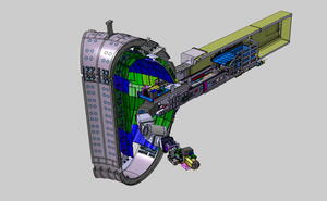
Multi-jack hydraulic devices called TIPI tables will move the toroidal field coils in all three directions (left and right, up and down, forward and backward) until their target position is reached.
TIPI (for Toroidal Field Coil In-Pit Installation Tool) tables are multi-jack hydraulic devices that can move the load they support in all three directions (left and right, up and down, forward and backward).Three such tables, two located outboard, one inboard supported by the central column, are operated jointly to position the sector modules.Under each of the toroidal field coils that descend into the tokamak pit as part of a sector module, a sturdy steel purpose-built tool called the “outboard bracket†acts as a cantilevered “foot†that will enable the TIPI table operators to position the coils above their final target—the pedestal-like gravity supports—and lower them to finalize alignment. (Once the coils are installed, the outboard brackets are removed.)
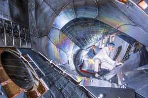
This image of the tools below the modules in the pit shows the complexity of the toroidal field coil alignment system. (1) points to one of the two outboard TIPI tables; (2) shows the cantilevered outboard bracket that enables the positioning of the coils on their (3) gravity support. (4) shows the juncture between the two modules, which are not yet aligned. (The blue structure in the photo is not connected to the alignment process.)
The module shift is done by five-millimetre increments, first on the pair of toroidal field coils, then on the vacuum vessel sector. As the step-by-step adjustment progresses, metrology plays an essential part by allowing the live tracking of the positioning operation with a precision of a few tenths of millimetres. By the end of the process, once the module’s target position has been validated by an extensive metrological survey, the toroidal field coils can be lowered onto the gravity supports and fastened, thus transferring the load to the building structure.
When a vacuum vessel sector is in its final position, it gets attached to the central column by way of an additional bracing tool bolted to its inboard section. This is to prevent movement in the case of a seismic event.
The position of each vacuum vessel, however, is deliberately set at a distance of approximately 5 millimetres from target. This gap will be closed at a later stage prior to transferring the load to a dedicated gravity support—something that can only happen once intercoil connections with adjacent sectors are in place. When the vacuum vessel is in its final position, it is attached to the central column by way of an additional bracing tool bolted to its inboard section. This, again, is to prevent movement in the case of a seismic event.Up to five intense workdays elapse between the landing of a module and the validation of alignment—definitive alignment for the toroidal field coils, still requiring a small adjustment for the vacuum vessel sectors.