you're currently reading the news digest published from 01 Apr 2019 to 08 Apr 2019
featured6
of-interest1
press10
featured
Neutral beam | The system that makes the Tokamak feel small
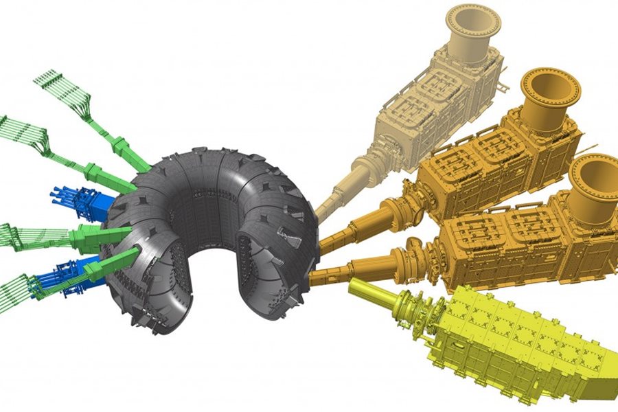
ITER is a big machine—by far the largest fusion device ever built. But there is a system just a few metres away that makes it look like a mere appendage to something much larger. The neutral beam system, with its three, possibly four, massive injectors is the real beast at the heart of the ITER installation. Construction work underway in the Tokamak Building already gives a sense of how big the equipment for the neutral beam system will be. Giant circular cut-outs in the rebar at level 3 (L3) of the building—more than 3 metres in diameter each—will provide the passageway for high-voltage 'bushings,' which allow electrical power, cooling, and other services such as diagnostics to reach the neutral beam injectors hosted below. Just below the bushings, a vast, cavernous space has been reserved for the neutral beam cell where the beam injectors will be located. The largest devices (the heating neutral beam injectors) are sized like steam locomotives—25 metres long, 5 metres high and 5 metres wide—with a chimney-like bushing reaching up 9 metres to connect to the openings on the third floor. The injectors will be connected to the Tokamak at L1 level—exactly across from the Tokamak's mid-plane and the equatorial port openings. A neutral beam injector is essentially a particle accelerator. Its function is to deliver high-energy particles to the heart of the plasma. ITER is planning two one-million-volt (MV), 40A heating neutral beam injectors (and is making a space reservation for a possible third) as well as a smaller neutral beam line (100 kV, 60A) for diagnostic purpose. The heating neutral beam injectors will each contribute 16.5 MW of heating power to the plasma; the diagnostics neutral beam will provide information on the helium ash density produced by the D-T fusion reactions in the fusion plasma. At the entry end of the heating neutral beam, a beam source generates the electrically charged deuterium ions that are accelerated through a succession of five grids (each separated by a 200 kV electrical potential) to the required energy of 1 MV at the exit end of the beam source, a 'neutralizer' rips them of their electrical charges to become 'neutrals,' allowing them to penetrate the Tokamak's magnetic cage and, by way of multiple collisions with the particles inside the plasma, raise plasma temperature to the point where fusion reactions can occur. The heating neutral beams are designed to be able to operate during the entire plasma duration, up to 3,600 seconds. Neutral beams are routinely used in tokamak devices as the workhorses of auxiliary heating. In ITER however they will be considerably larger and more powerful than in any previous fusion device. Generating a 1 MV beam that will deliver 16.5 MW to the plasma requires a unique power infrastructure. Located just outside the Tokamak Complex, two large buildings will host the transformers, the AC/DC converters and the vast high-voltage hall that will feed power to the neutral beam system by way of transmission lines entering the Tokamak Building through the 'north wall' at the L3 level. There is only one example of a high-voltage installation more powerful than ITER's. In China, where high-voltage DC current is used to deliver electrical power to populations far away from the productions sites, a 1.2 MV system was recently established to push power from Xinjiang, in the northeast corner of the country, to the megacities in the east—1.2 MV in China for a 3,000-kilometre distance; 1 MV in ITER for slightly more than one hundred metres ...
Image of the week | Sandblasting
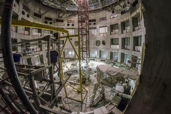
Whether at home or in a nuclear installation, a painting job begins with surface preparation. In the ITER Tokamak Pit, close to 3,000 square metres of wall need to be sandblasted prior to being coated with thick, smooth, decontaminable 'nuclear paint.' Working in two shifts from five suspended platforms, workers have used more than 30 tonnes of abrasive sand to create a rough surface that optimizes paint adherence. The operation, which began in mid-March, should be finalized this week. Painting will begin in earnest shortly, as soon as hot air blowers have brought the vast volume of the Pit (25,000 cubic metres) to the required temperature of ~20 °C.
Component transport | Way now open for Japan's "super HEL"
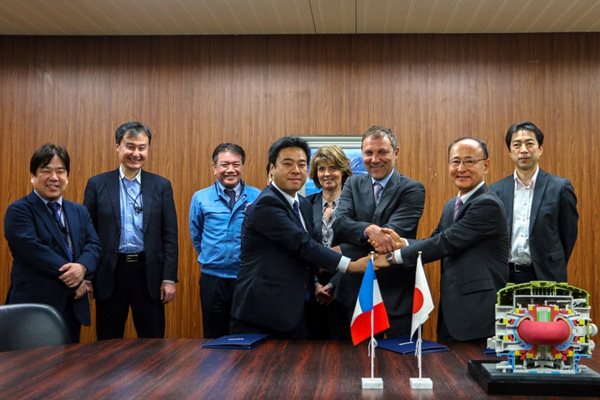
The largest machine components and plant systems delivered to ITER by the seven Members fit into two main logistics categories¹—Conventional Exceptional Loads (CEL), delivered along regular roads, and Highly Exceptional Loads (HEL), which must travel along the dedicated ITER Itinerary. Within this last category one sub-group stands out—the 'super HEL,' comprising 30 of the largest, heaviest and most awesome ITER components. Anything heavier than 60 tonnes—or with dimensions exceeding 5 metres in height and/or width—is considered an HEL and must travel the route that was specially adapted for ITER components. Out of an estimated 300 HEL planned, 70 have already reached ITER. The most impressive loads, however, are yet to come. Toroidal field coil #12, scheduled to dock at the Marseille-Fos harbour late this year, will be among the first 'super HEL' to be delivered to ITER.² The D-shaped magnet, 18.5 metres in height and weighing more than 500 tonnes, is nearing completion under the supervision of the Japanese Domestic Agency QST at Mitsubishi Heavy Industry's Futami facility. Transporting such a massive and valuable component halfway around the world requires not only a lot of technical preparation, but also a precise regulatory framework. On 7 March, ITER global logistics provider DAHER, its local partner Hitachi Transportation System, and QST signed the implementation agreement that opens the way to the delivery of all the super-HEL components procured by the Japanese Domestic Agency. 'The transport and delivery of this first toroidal field coil opens a new chapter in our collaboration with ITER,' says François Genevey, the ITER Transport Project Director at DAHER. Like all the other super-HEL components expected to be delivered—the other 18 toroidal field coils³, the 2 poloidal field coils manufactured off site, and 9 vacuum vessel sectors—toroidal field coil #12 will travel in a highly sophisticated transport frame that is currently under design at Mitsubishi Heavy Industry and Toshiba. The structure will be equipped with protective elements (dense polymer pads, acceleration absorbers) to mitigate the effect of movement or acceleration and to diffuse the stresses that will inevitably occur during the long sea voyage and transshipment operations. ¹ About 10,000 components fall into the category of 'Conventional Loads,' 3,000 are 'Conventional Exceptional Loads' and 300 are 'Highly Exceptional Loads.' ² Poloidal field coil #6, manufactured in China under a European contract, and toroidal field coil #9 procured by Europe are the other 'super HEL' scheduled for delivery before the end of the year. ³ 18 toroidal field coils are needed for the machine, plus one spare.
Diagnostic feedthroughs | Positioned at the vacuum boundary
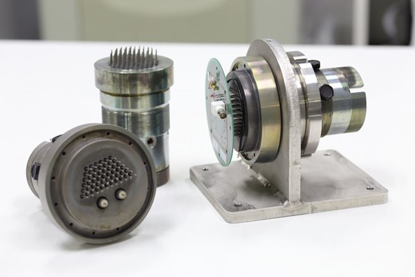
The design is advancing in Europe on a large set of components—electrical feedthroughs—that will be installed at the barrier between the air atmosphere outside the vacuum vessel and the ultra-high vacuum environment on the inside. The feedthroughs will service diagnostic and instrumentation clients inside of the vessel, allowing electrical signals and power to pass without compromising the vacuum inside the machine. Clients include almost all of the diagnostics and instrumentation systems mounted on the vacuum vessel inner wall, the divertor cassettes, or the diagnostic racks of the lower ports, and which have electric signal transmission or power requirements. A number of requirements make these components particularly challenging to design—the large number of client systems (each with different requirements for their transmission chain); the nuclear environment—both in terms of radiation dose and safety regulations for protection-important components (PIC); the strict requirements on materials and leak rates to maintain ultra-high vacuum conditions; and the fact that the feedthroughs have to be installed before First Plasma but operate throughout the four phases of the machine without maintenance. Many of these challenges have previously been achieved in isolation, but ITER brings them all together for the first time. Based on a Procurement Arrangement signed with the ITER Organization in 2017, the European Domestic Agency Fusion for Energy is responsible for the procurement of more than 70 diagnostic feedthroughs. It is working closely with IDOM (Spain) on this project, and recently the preliminary design was approved during a formal review process by a panel composed of staff from Fusion for Energy and the ITER Organization. Electrical feedthroughs for ultra-high vacuum usually consist of an array of metal pins sealed into a disc using a glass-to-metal or ceramic-to-metal seal—with one barrier or wall between the vacuum and the air. IDOM's approach is to use two glass-to-metal seals—one at each end of a metal pin—with an interspace between the seals. This creates a double wall or double barrier between the vacuum inside of the ITER machine and the air atmosphere of the port cell interspace, which answers to both safety and vacuum requirements. The interspace volume between the seals can be monitored to detect any leaks while the double wall provides increased reliability and defence in depth. 'These feedthroughs are responsible for carrying almost all of the thousands of electrical signals through the ITER vacuum vessel's first safety boundary,' says Michael Walsh, head of the ITER Port Plugs & Diagnostics Integration Division. 'Their reliability is very important to our mission. We are delighted to see the good progress in the work.' The next step will be to develop a fully qualified final design. Please see the original report on the Fusion for Energy website.
Platform | The future
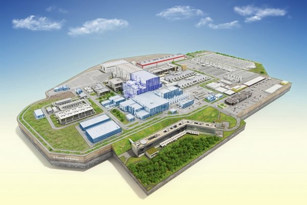
In a few years, reality will reflect this artist's rendition of the completed ITER platform. Civil work on the ITER site is approximately 70 percent achieved for First Plasma building scope. In this diagram, buildings that do not yet exist are coloured in light blue—for example the neutral beam power infrastructure (centre right), the ITER Hot Cell Building (centre left) and the Control Building (left). The Tokamak Complex is coloured in light mauve because—although its concrete walls have reached their maximum height (except in the Tritium Building)—it does not yet have its 'steel cap.' Once achieved, the steel structure will create a vast open space for the bridge cranes to deliver machine components to the Tokamak Pit. And of course, down the road, the entire Tokamak Complex will be clad with the stainless steel that has been for many years now the architectural signature of ITER. This rendition was produced by Fusion for Energy's Martial Boulguy. For a high-resolution pdf version (uncoloured), please see ITER posters here.
Lower cylinder | Sealed away in its cocoon
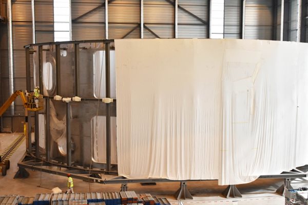
To make room in the Cryostat Workshop for the assembly of the upper cylinder, contractors are preparing the completed lower cylinder for storage outside on the platform. The process involves reams of synthetic 'cocooning' material and sprayable glue. The 'mothballing' technique for the lower cylinder is designed and implemented by Cocoon Holland, a specialist in weatherproof storage solutions. Mid-April, the mega-doors of the Cryostat Workshop will open to allow the lower cylinder to be removed on a self-propelled modular transporter. The 375-tonne component will be dressed all in white for the occasion, wrapped in layers of synthetic thermoplastic material that are 'melted' together through the application of sprayable glue. The synthetic skin that is formed seals the lower cylinder hermetically and protects it from weather, moisture and dust. Inside of the cocoon, the enclosed air is kept constantly circulating and humidity is maintained at a steady 38 percent—conditions that prevent the formation of corrosion or mould. The component will travel only a few dozen metres to a storage zone to the north of the Workshop. The transport path has been reinforced with airport-grade paving materials that can withstand pressures of up to 20 tonnes per cubic metre and large turning loads.
of-interest
Making a 1,000-tonne electromagnet
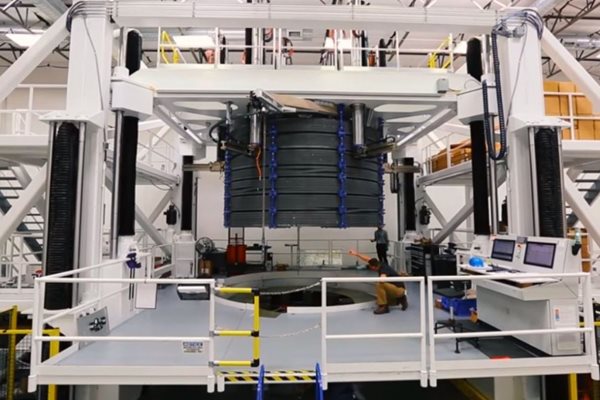
In this new photomontage by General Atomics and US ITER, watch how ITER's 1,000-tonne central electromagnet is fabricated in a specialized workshop in Poway, California. It takes approximately 22-24 months to manufacture one central solenoid module, and six are needed for the ITER machine (plus a seventh as a spare). © General Atomics/US ITER Click here to see the video.