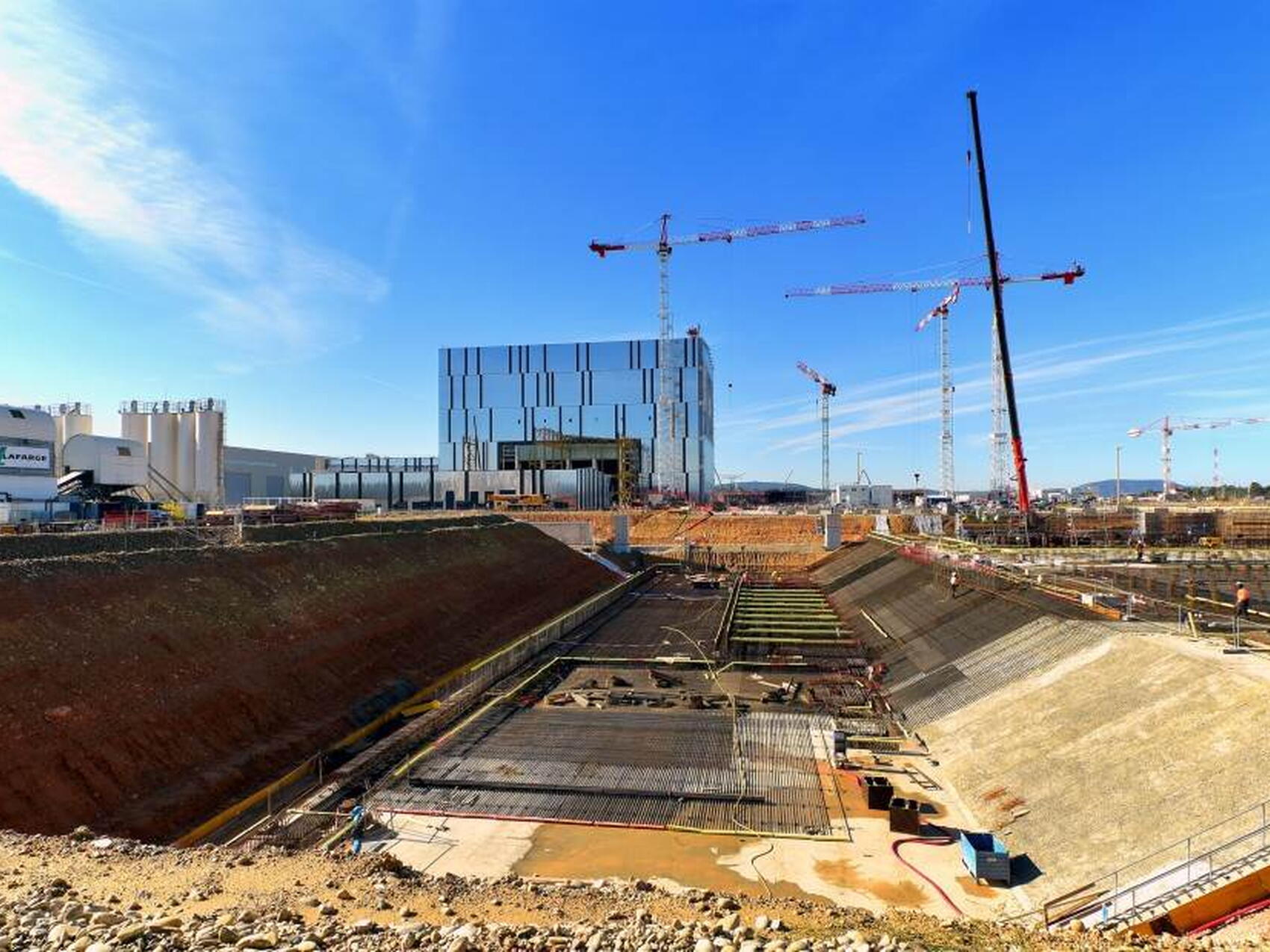
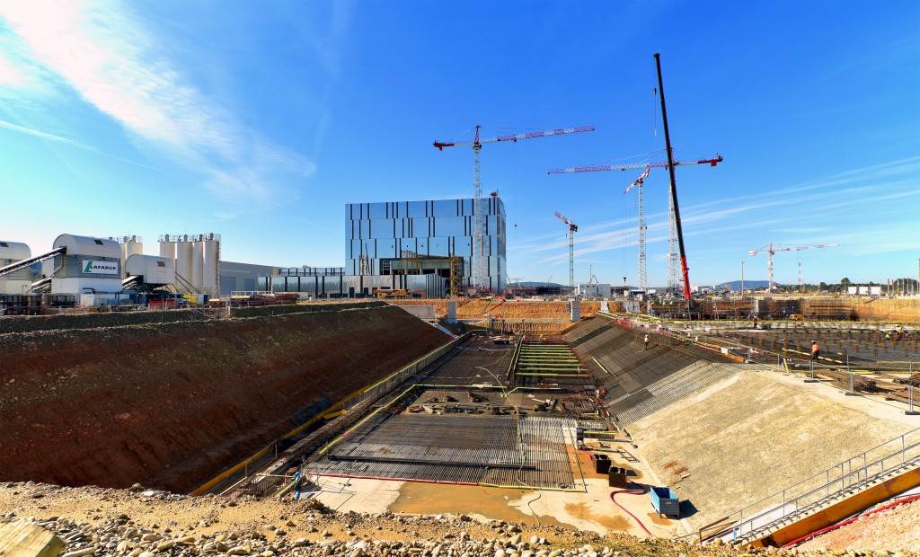
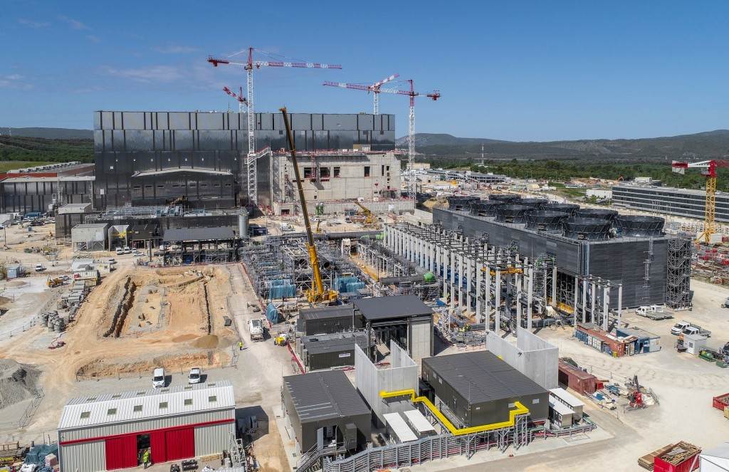
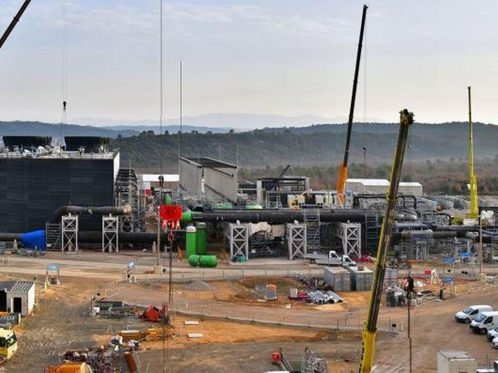
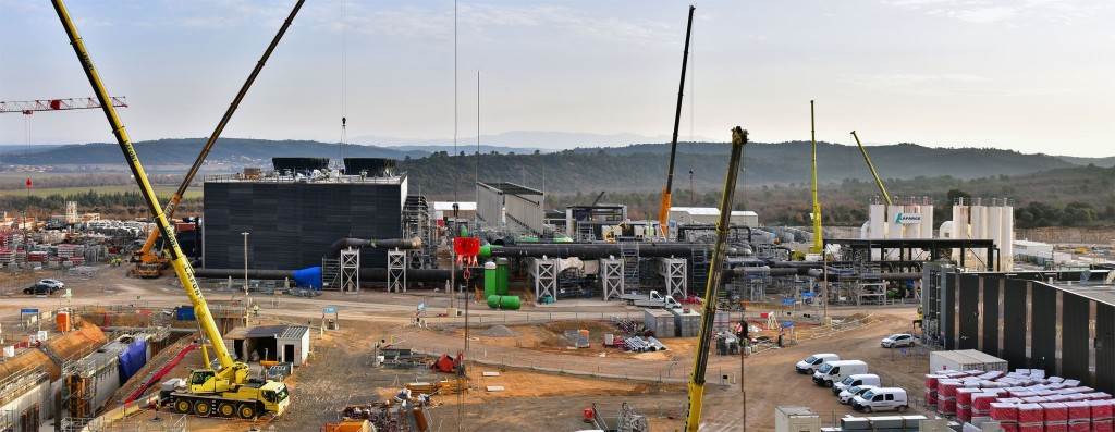
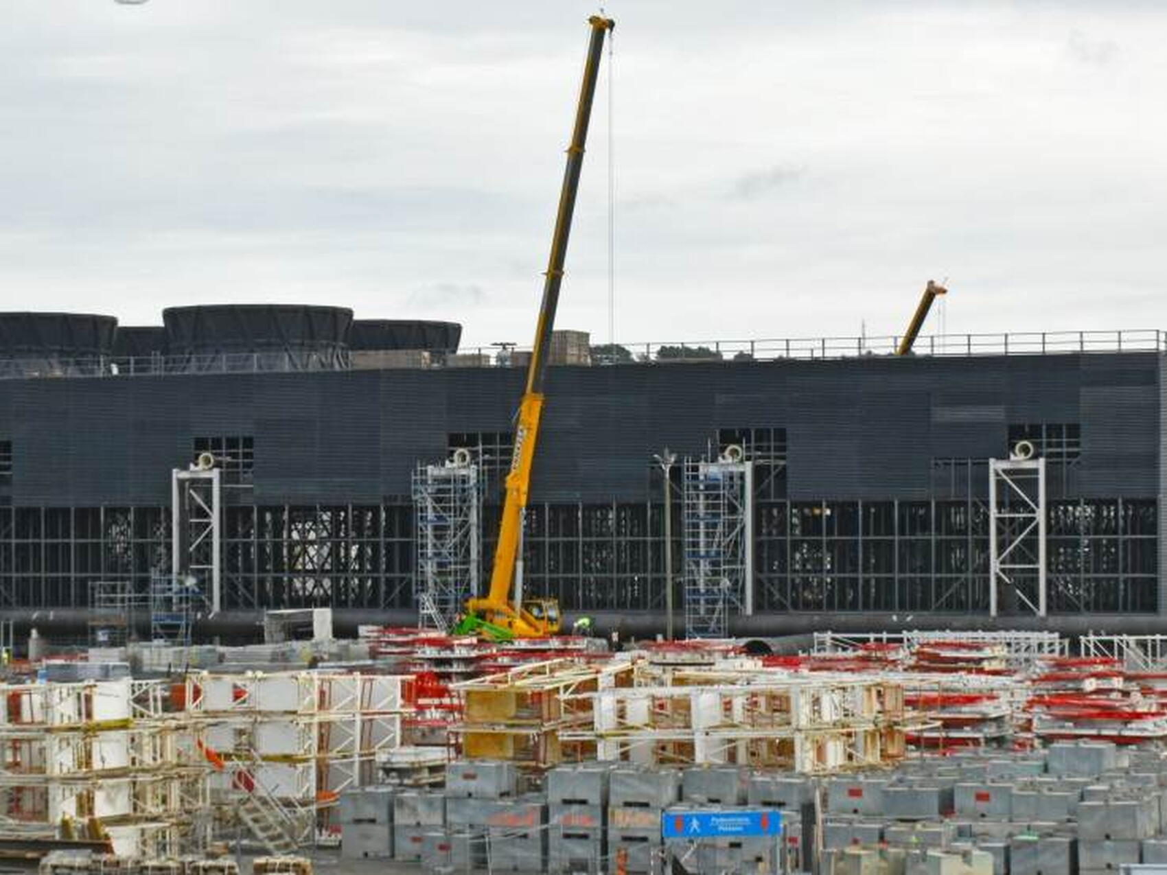
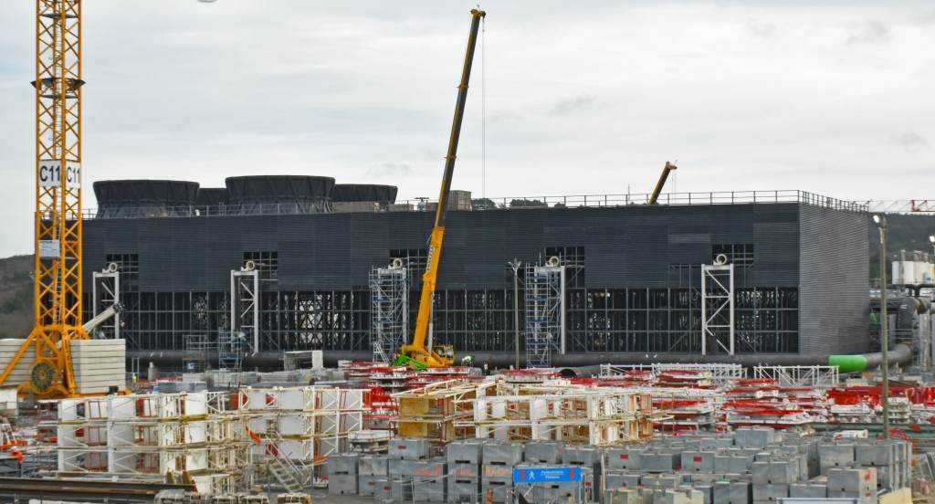
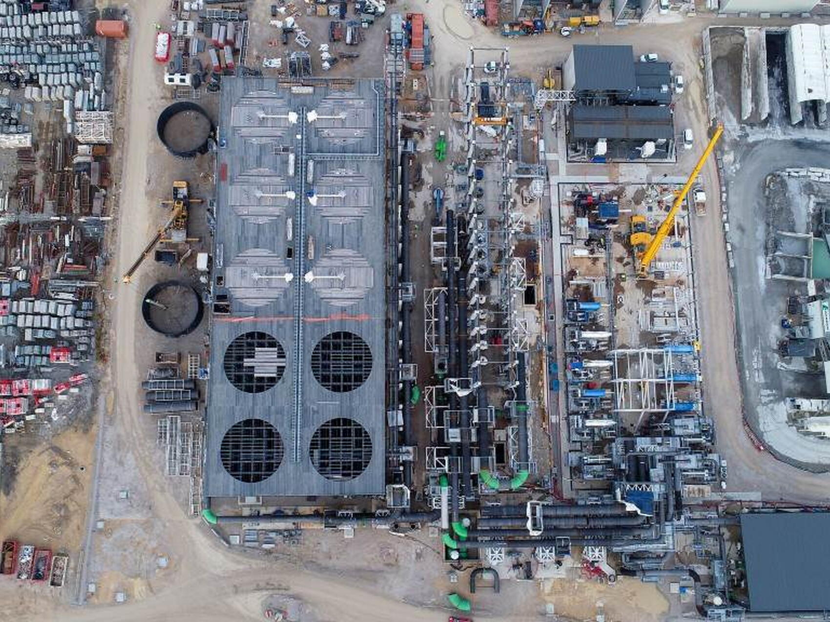
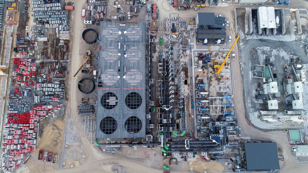
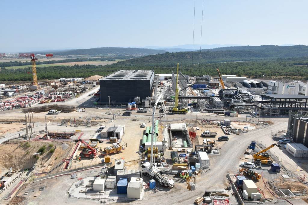
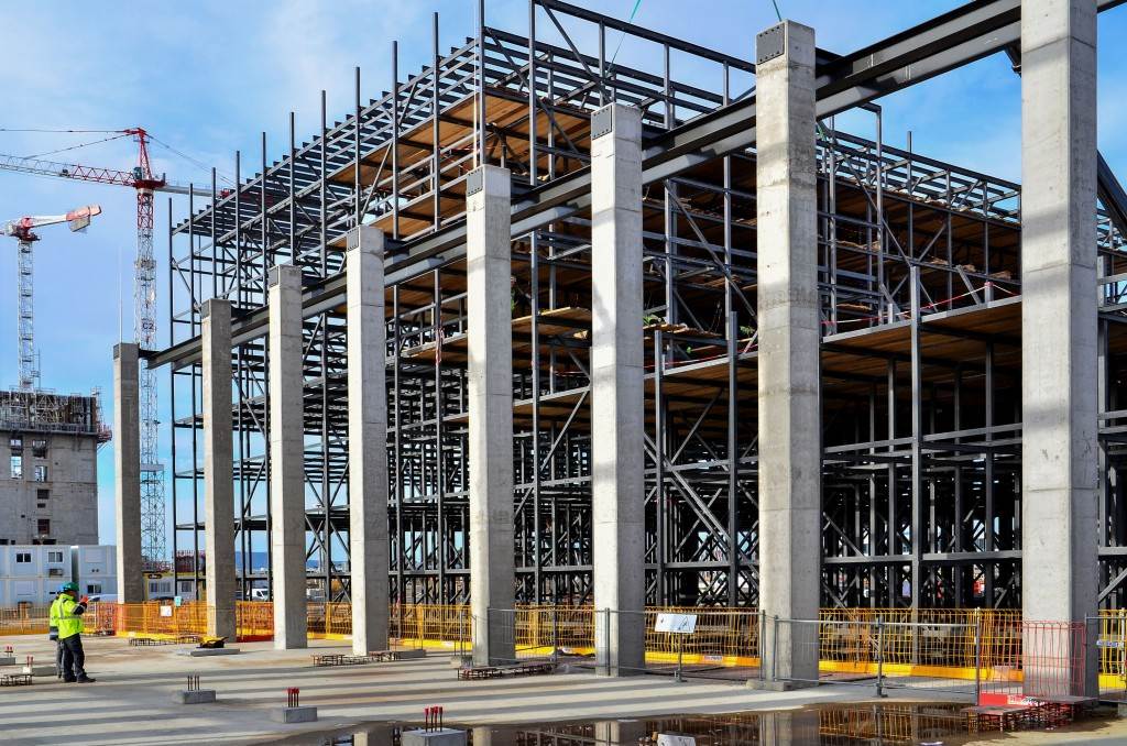
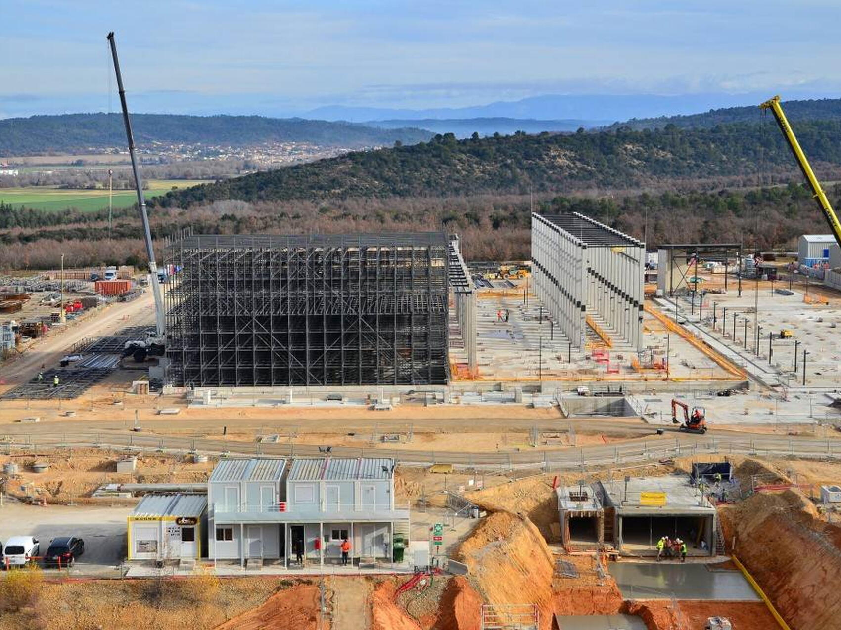
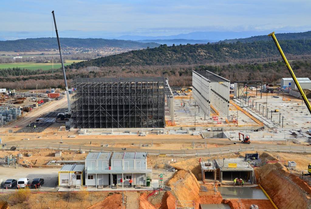
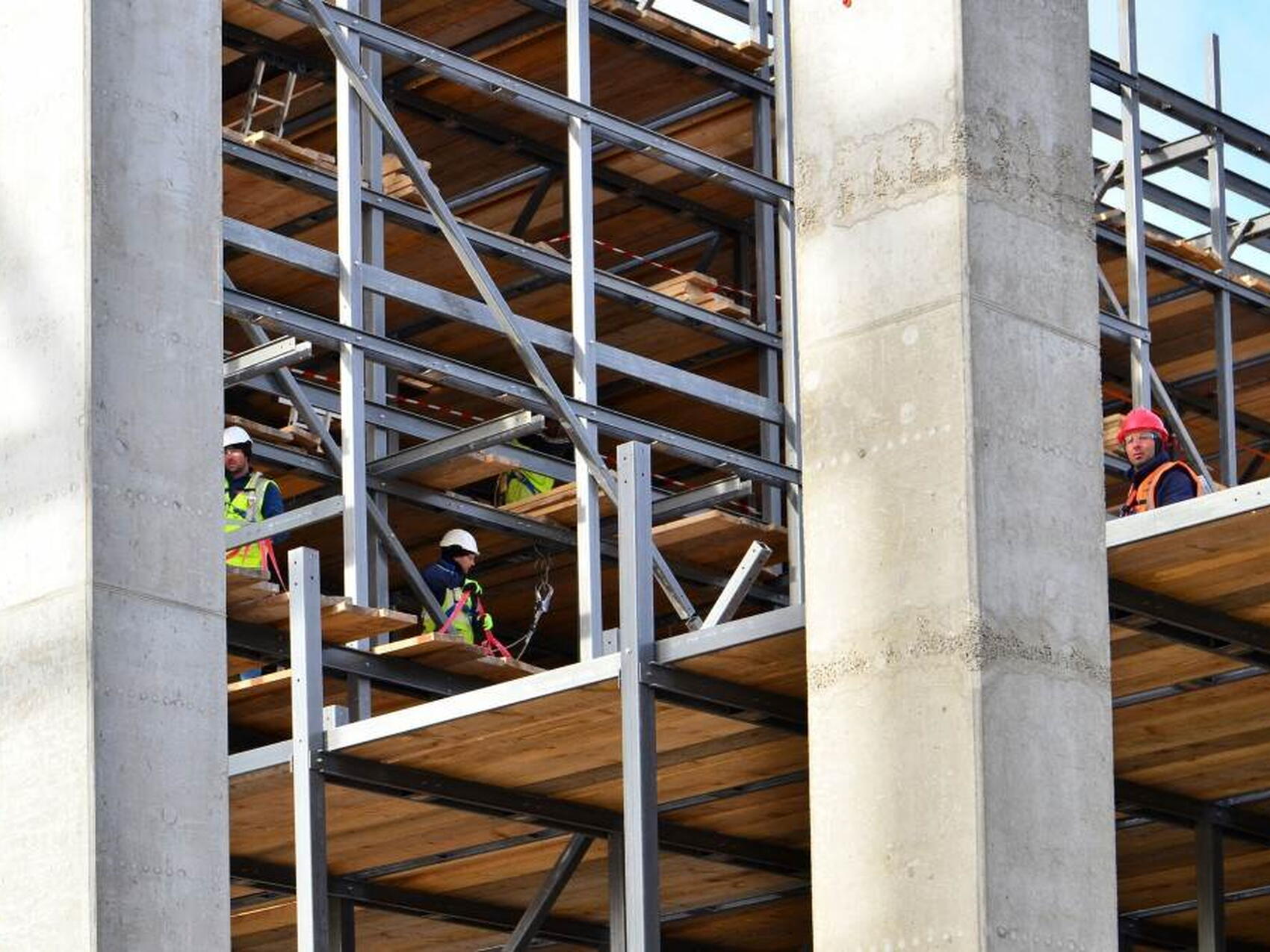
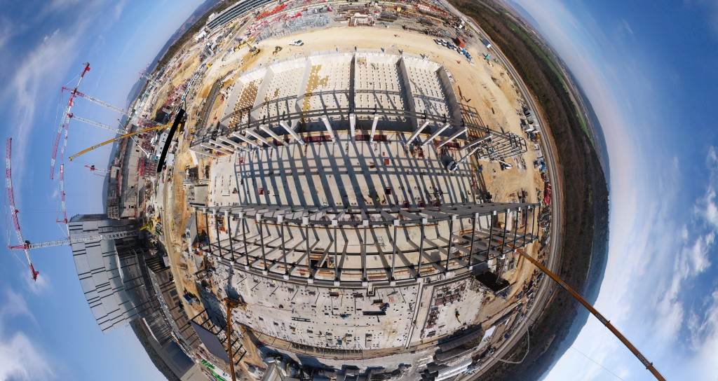
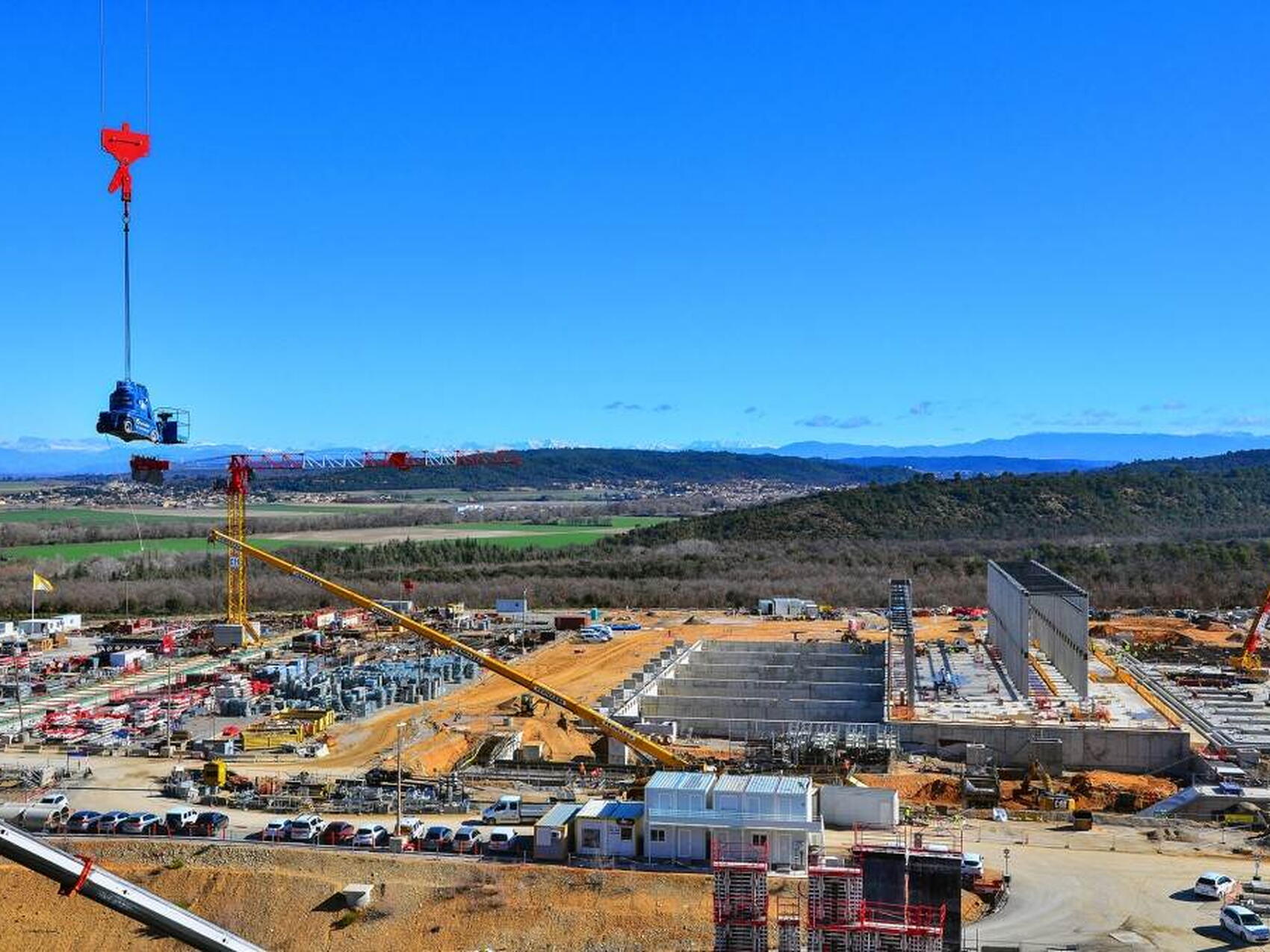
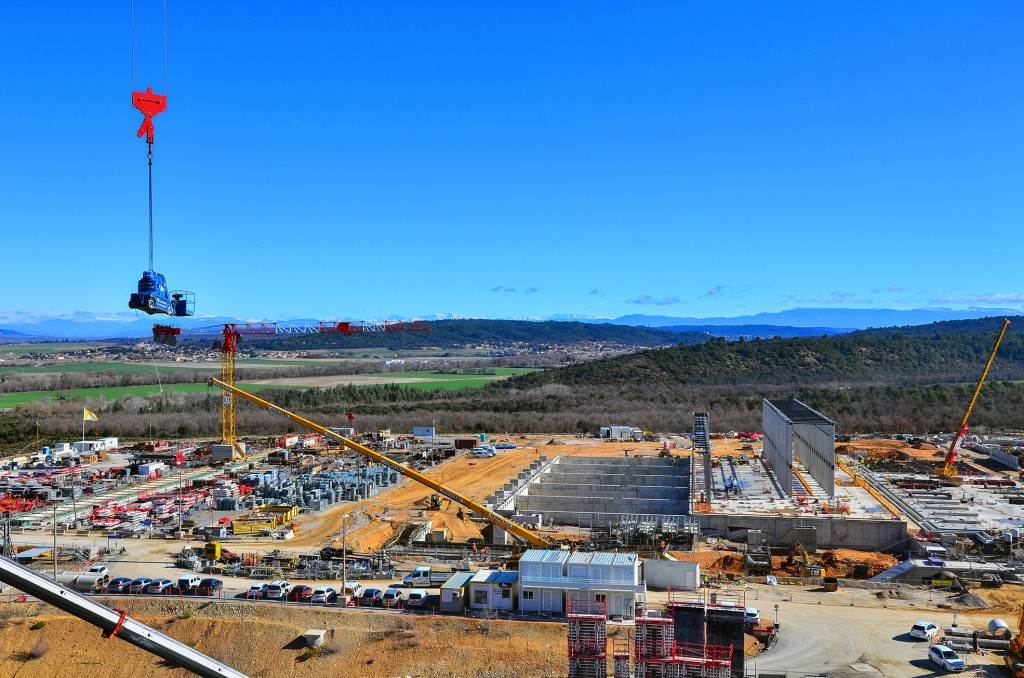
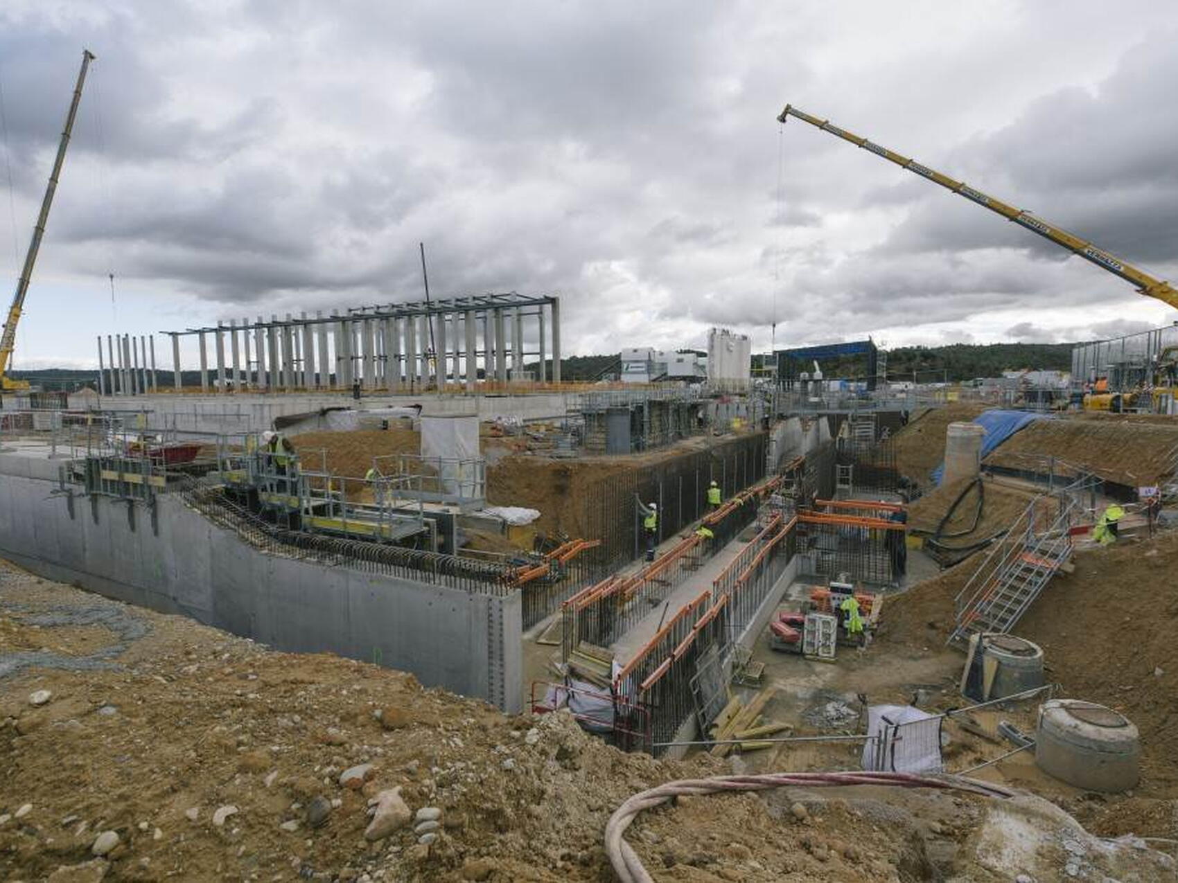
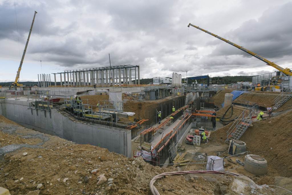
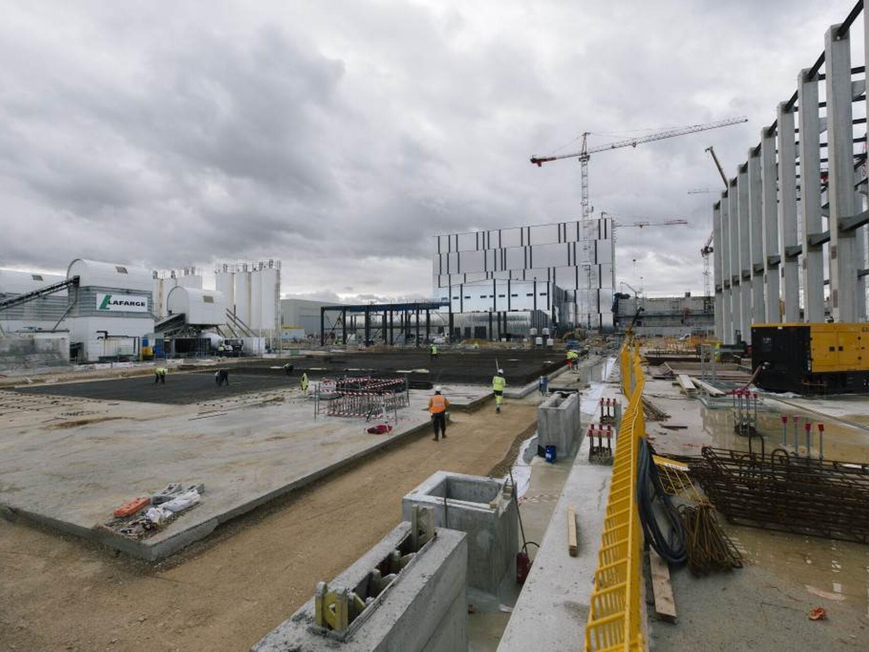
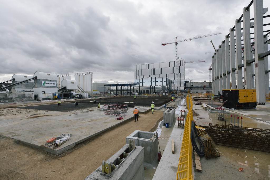
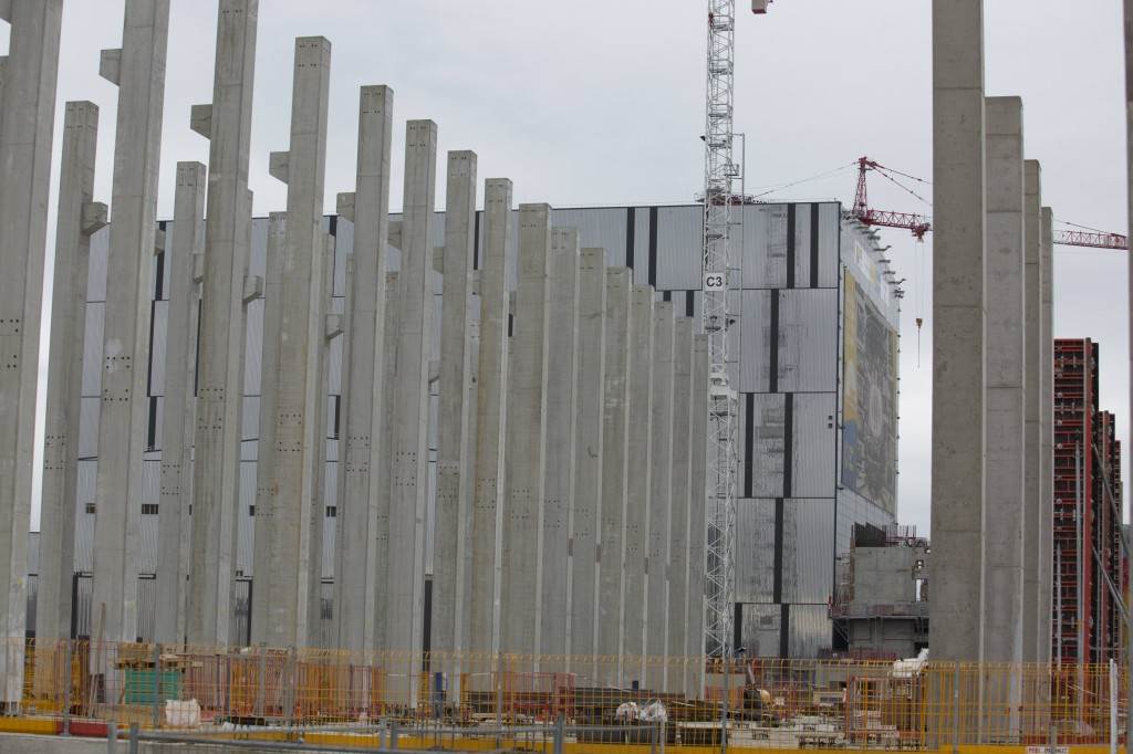
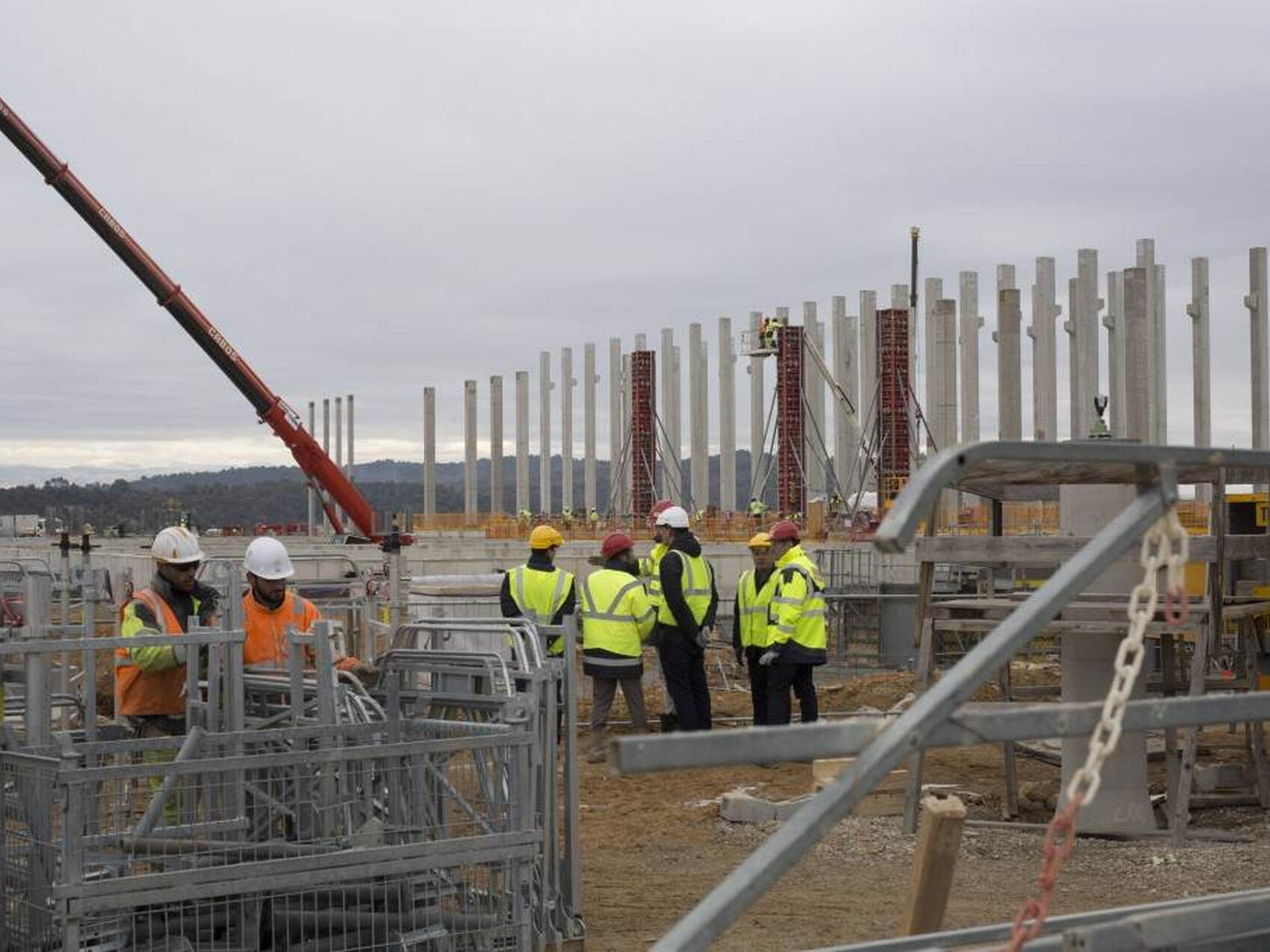
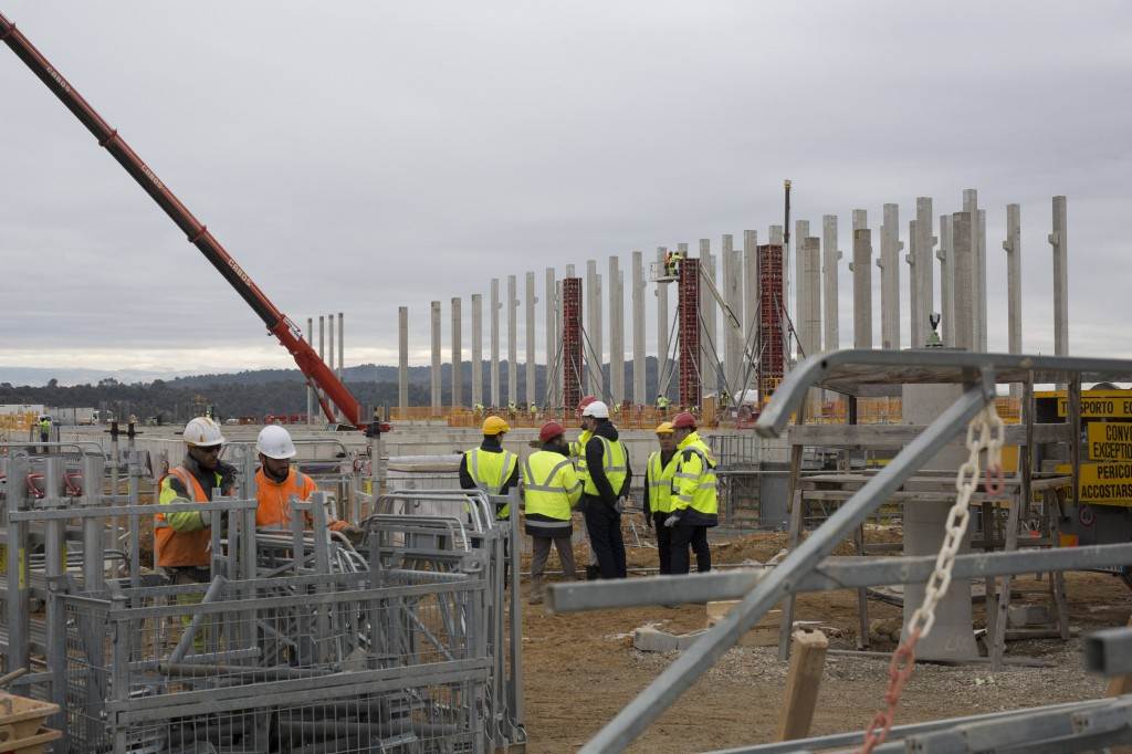
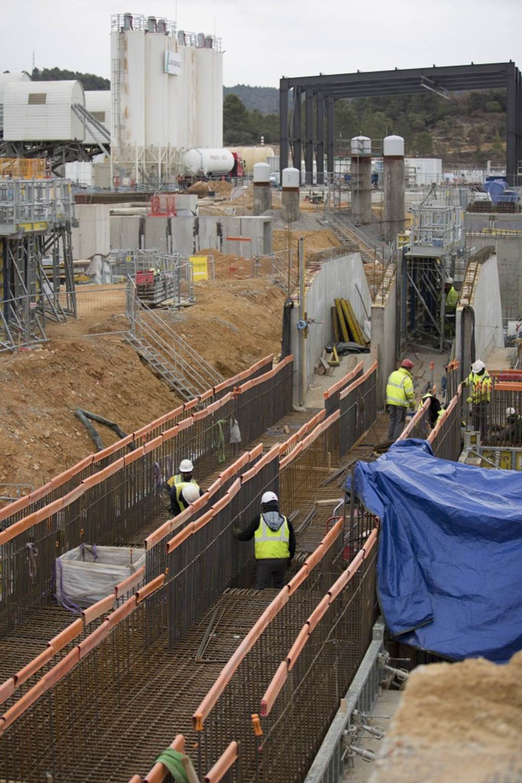
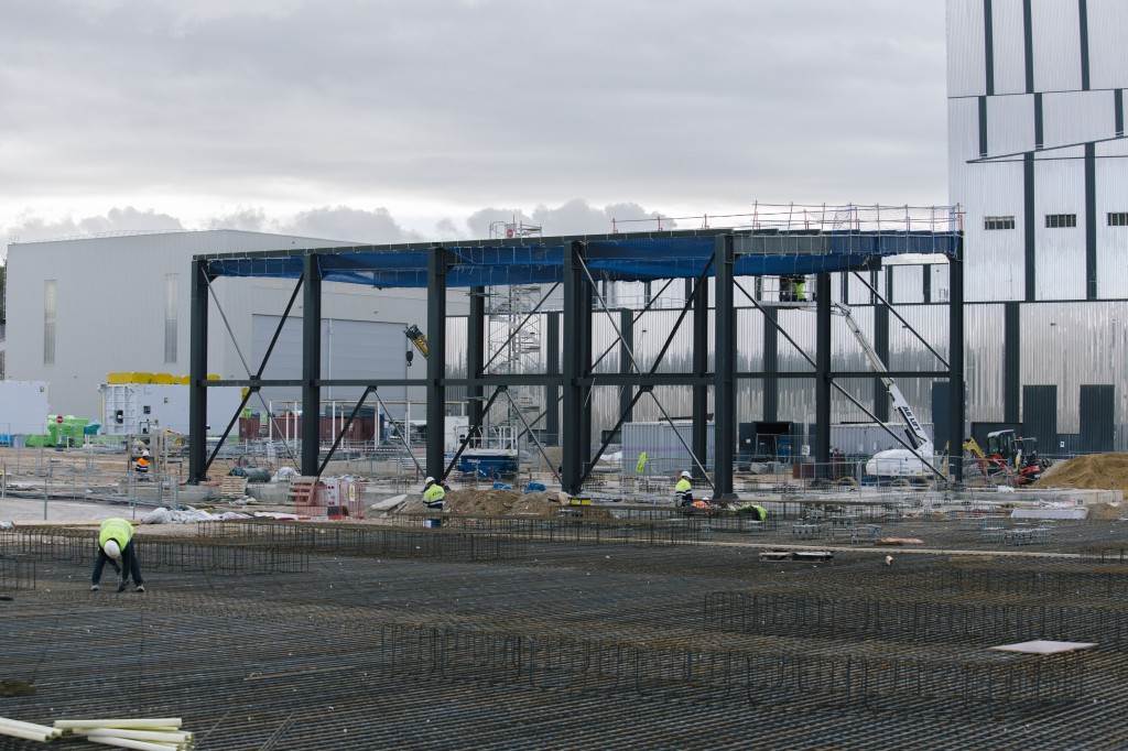
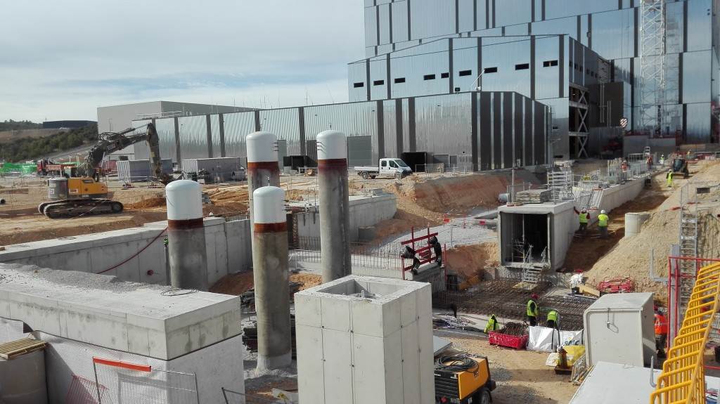
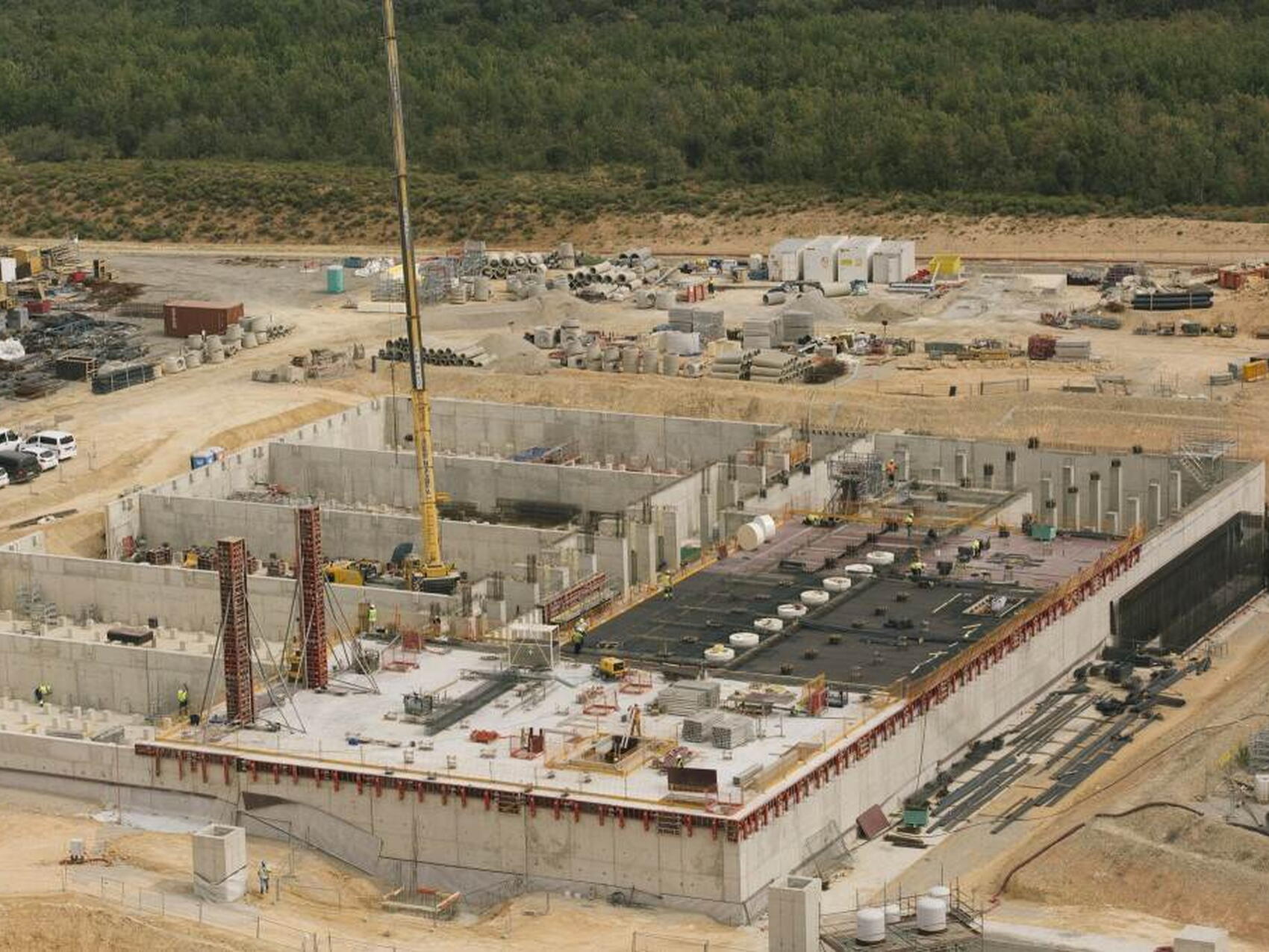
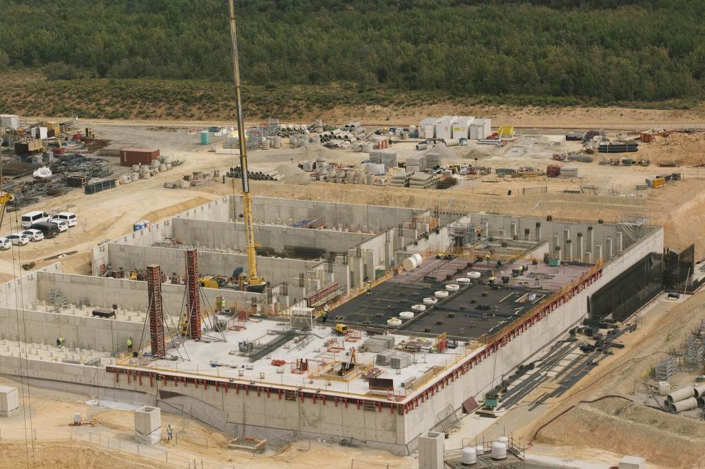
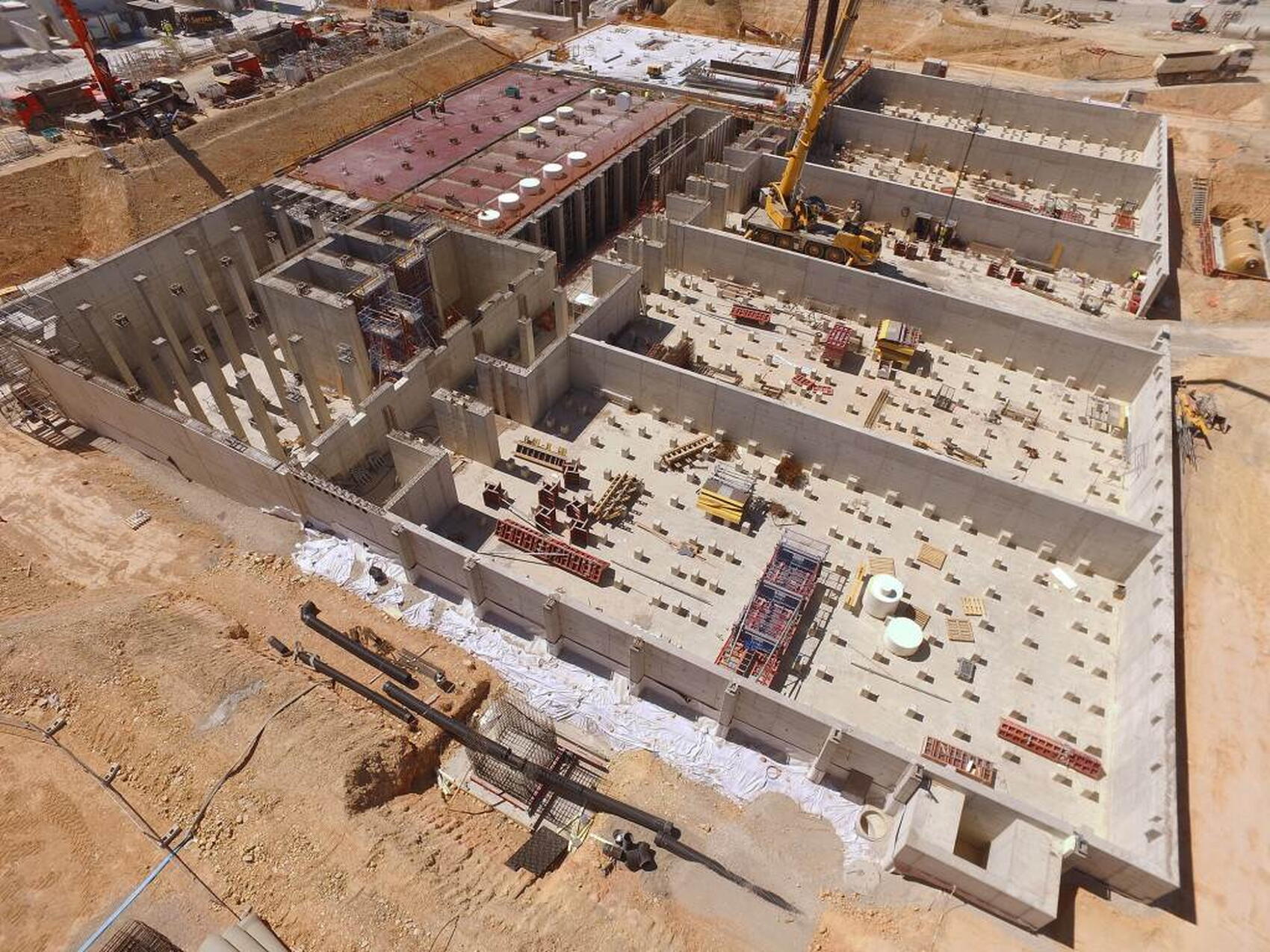
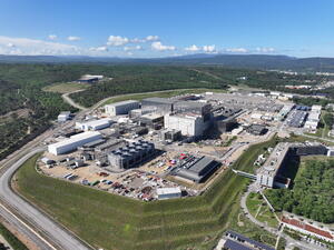
Cooling Tower Area
As an experimental device, ITER will not be exploiting the heat to generate electricity. Instead, the cooling water will be transferred through a cascade of cooling loops to a high-performance heat rejection system.
Cooling water circulating under pressure through the ITER installation is responsible for removing the heat load from the ITER vacuum vessel, its plasma-facing components, and plant systems such as heating and power systems.
As an experimental device, ITER will not be exploiting the heat to generate electricity. Instead, the cooling water will be transferred through a cascade of cooling loops to the heat rejection zone located on the northern edge of the platform, where it will be cooled using an evaporative process.
One of the challenges of designing the heat removal system has been to cope with the cyclic nature of ITER operation—the daily repetition of plasma pulses lasting 500 seconds, followed by 1300-second "dwell" periods. During the "burn" phase, the peak heat load reaches more than 1150 MW while during the dwell the heat load drops off significantly (to 160 MW), creating two distinct sets of process conditions for the system to manage.
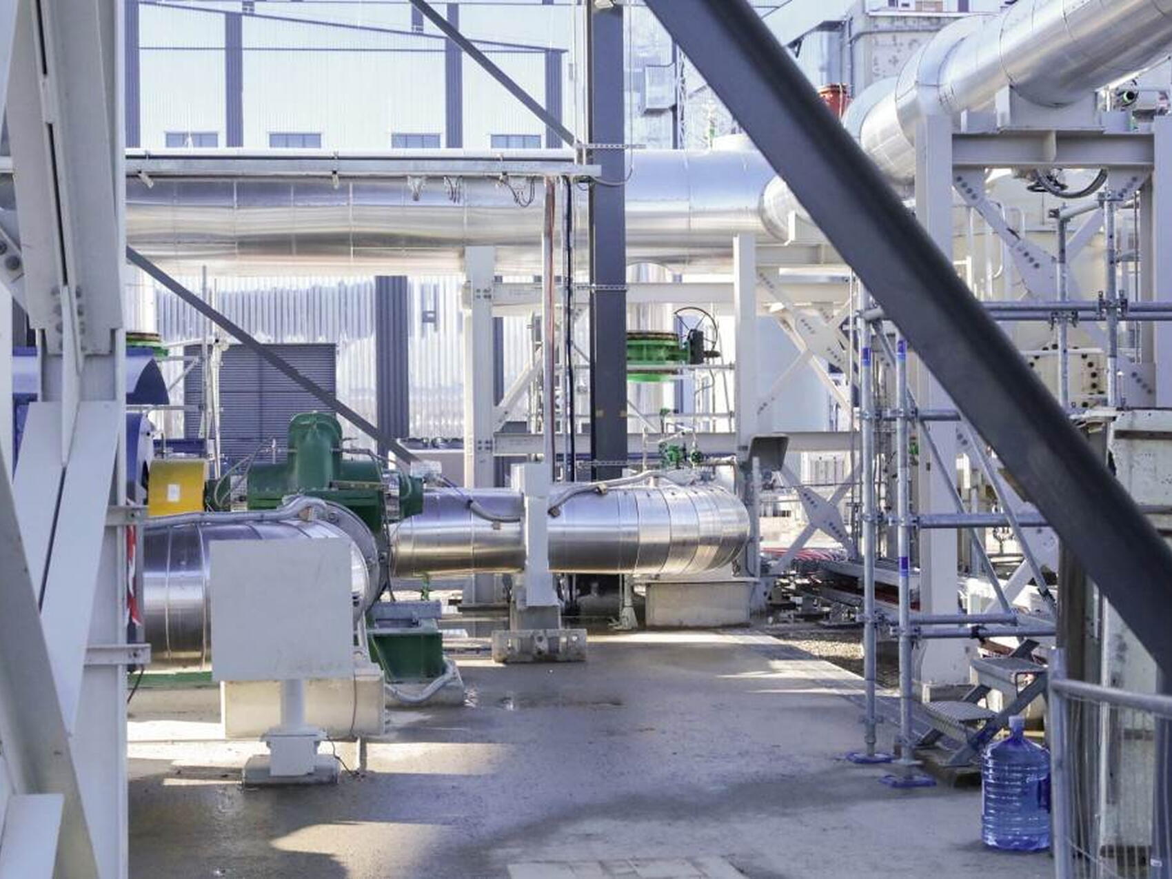
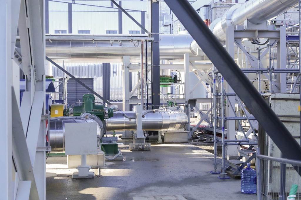
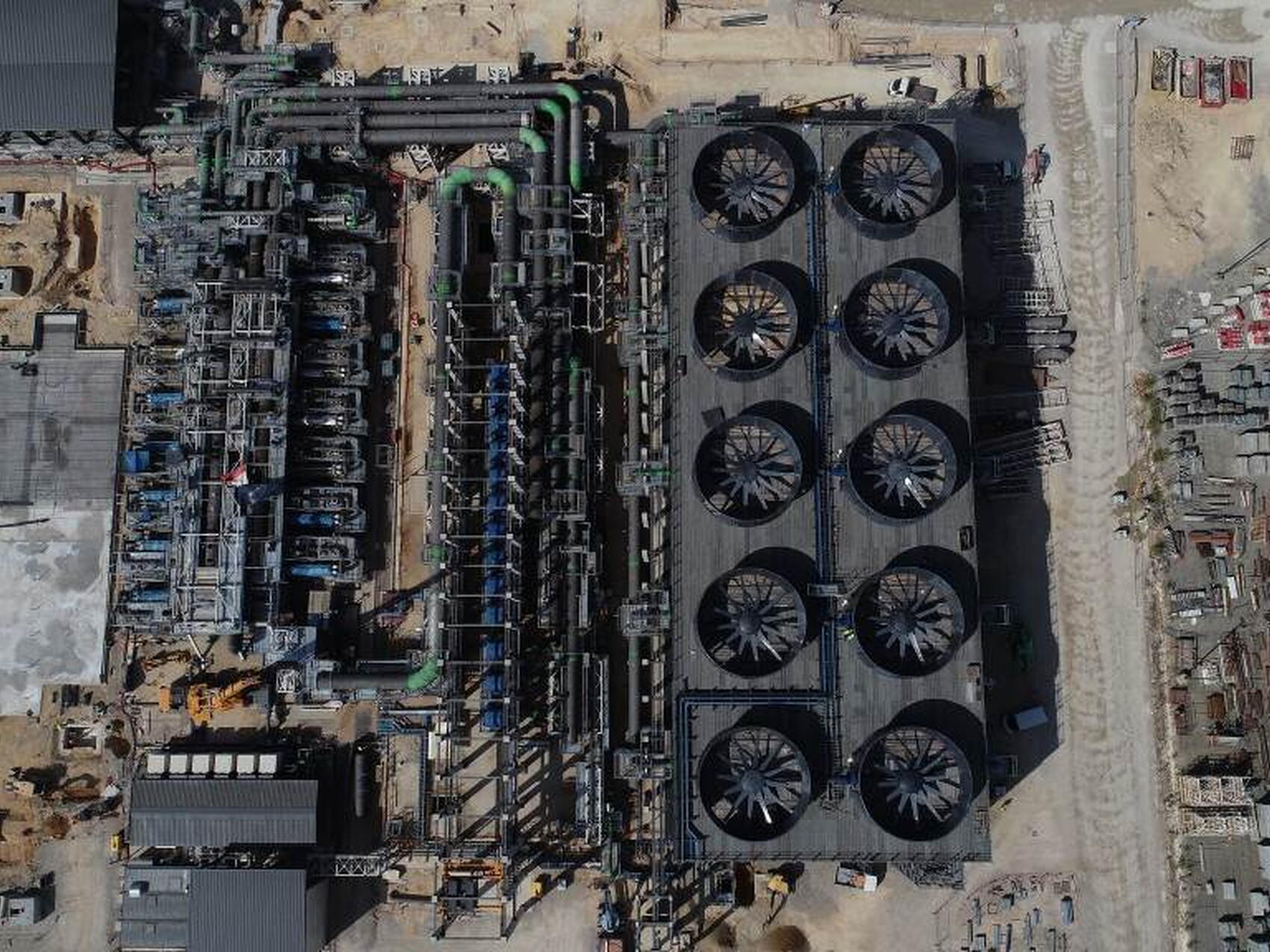
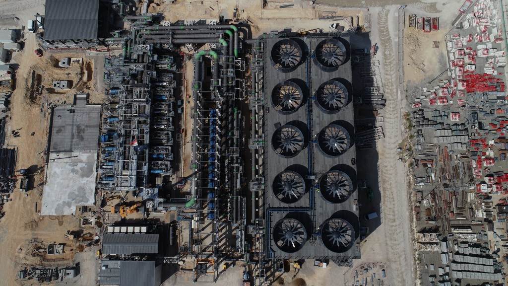
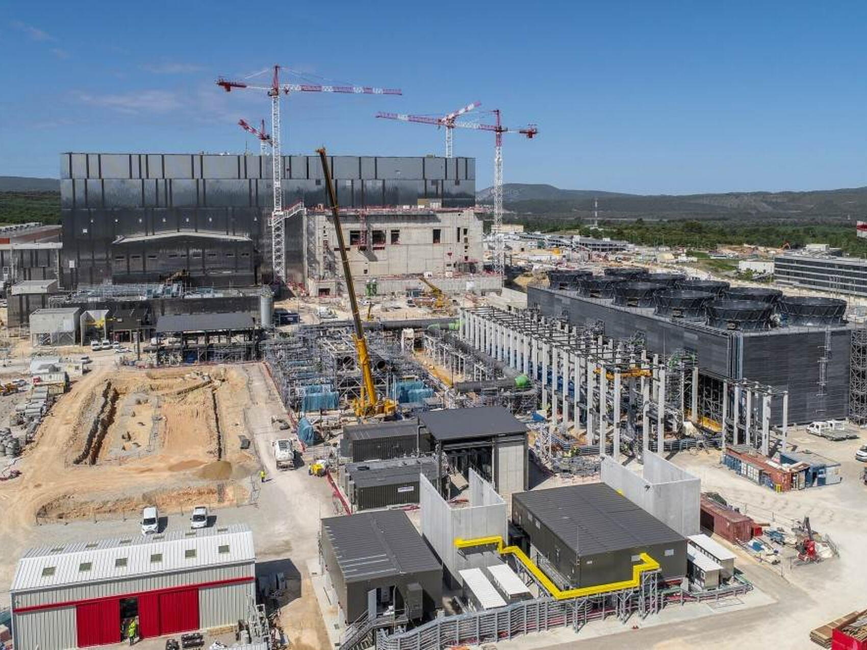
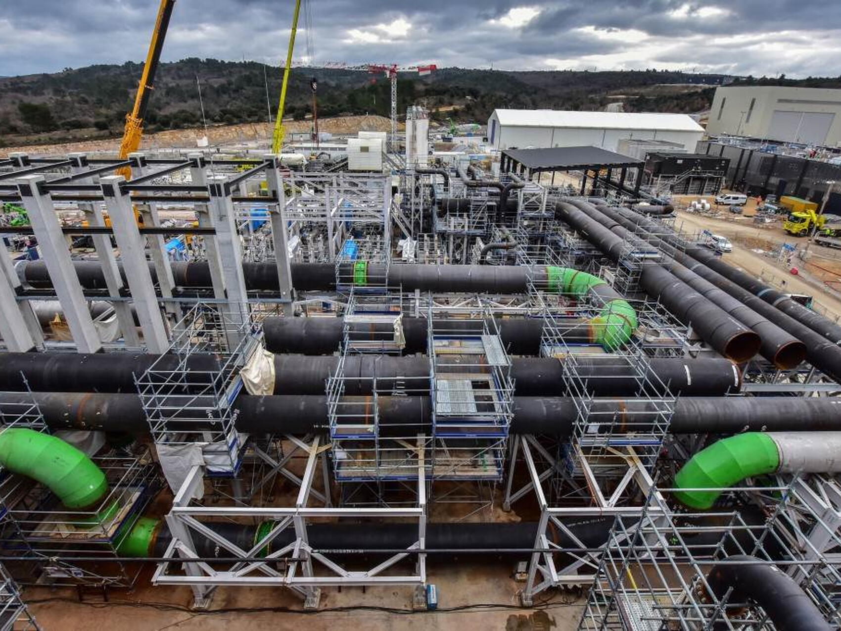
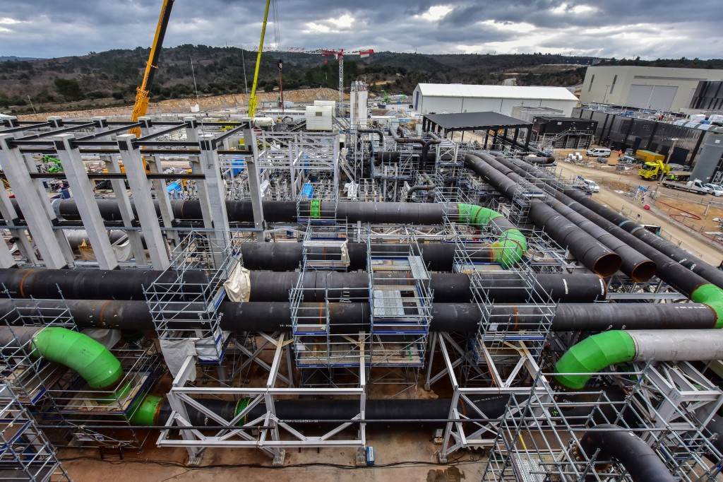
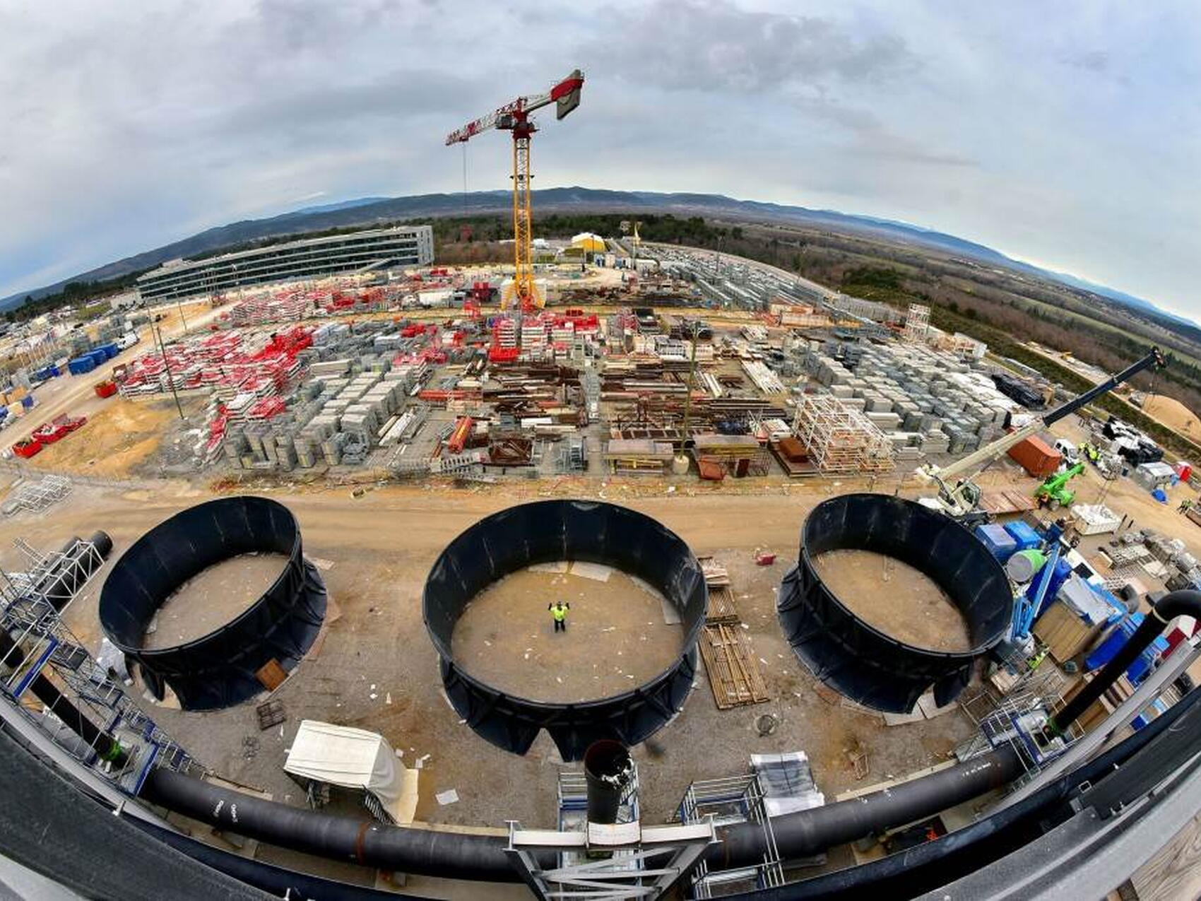
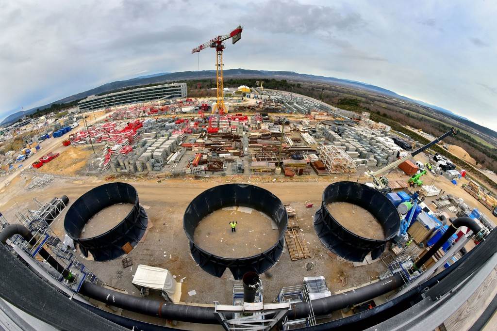
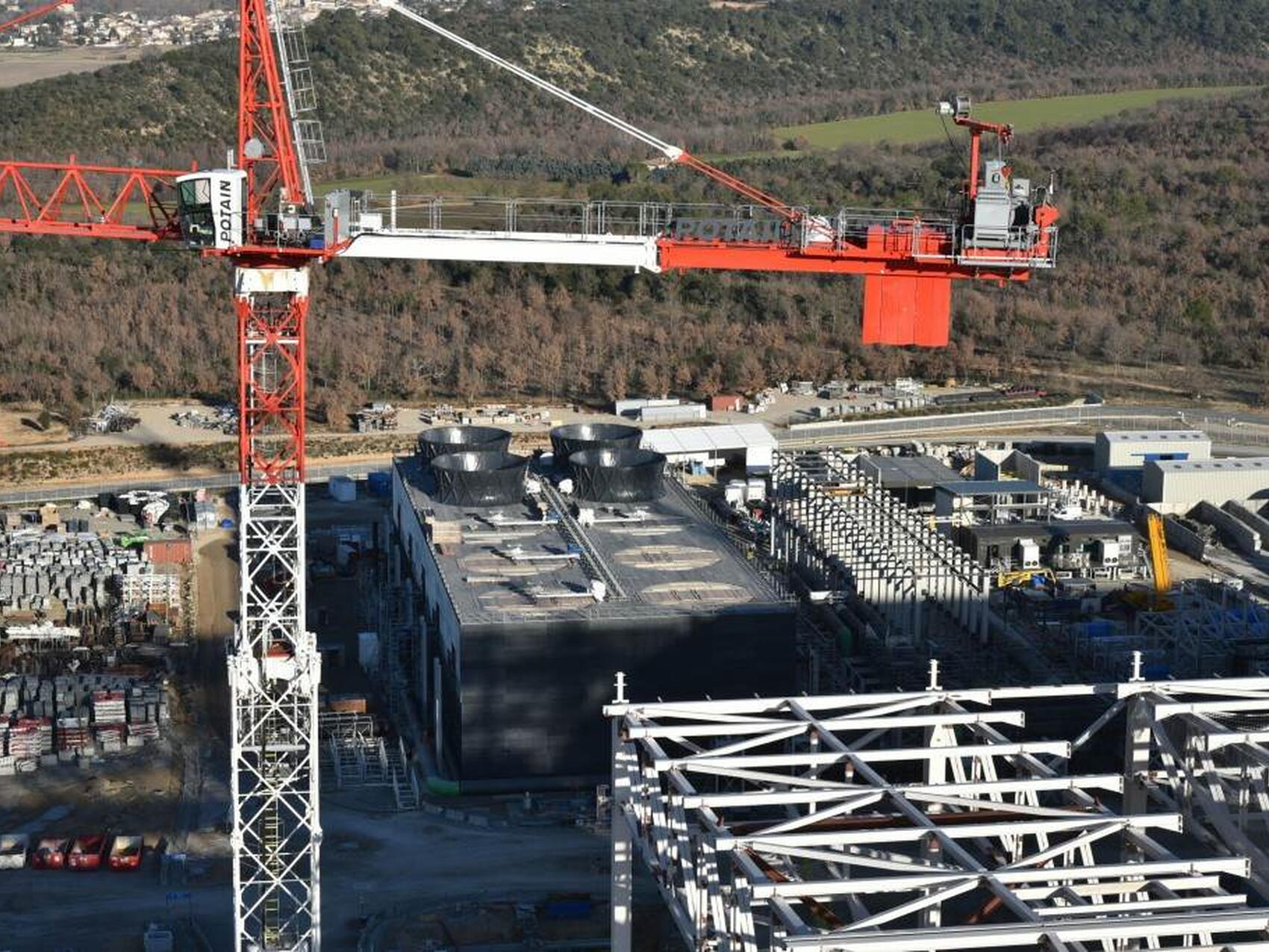
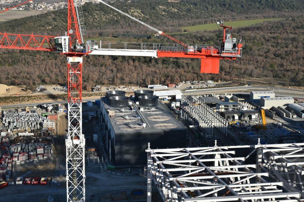
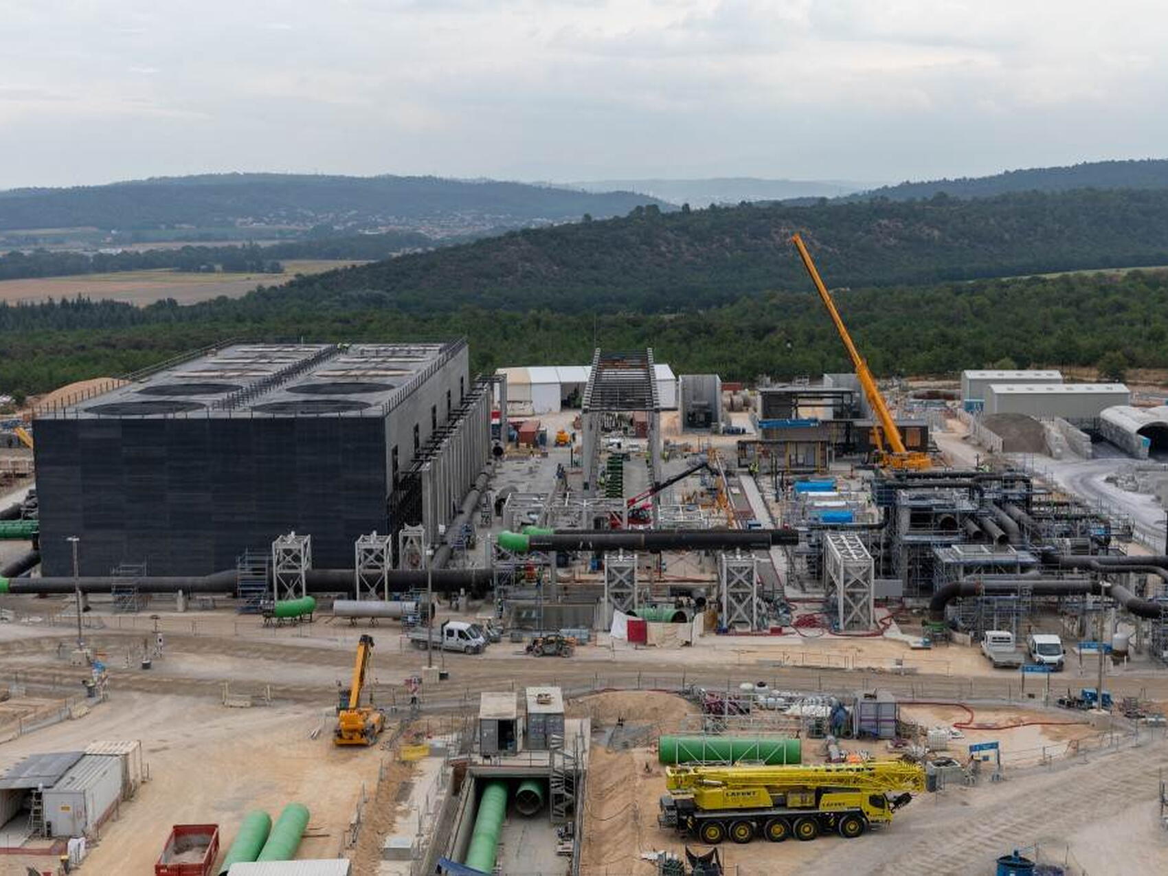
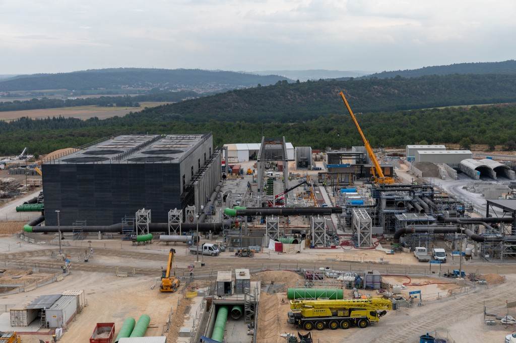
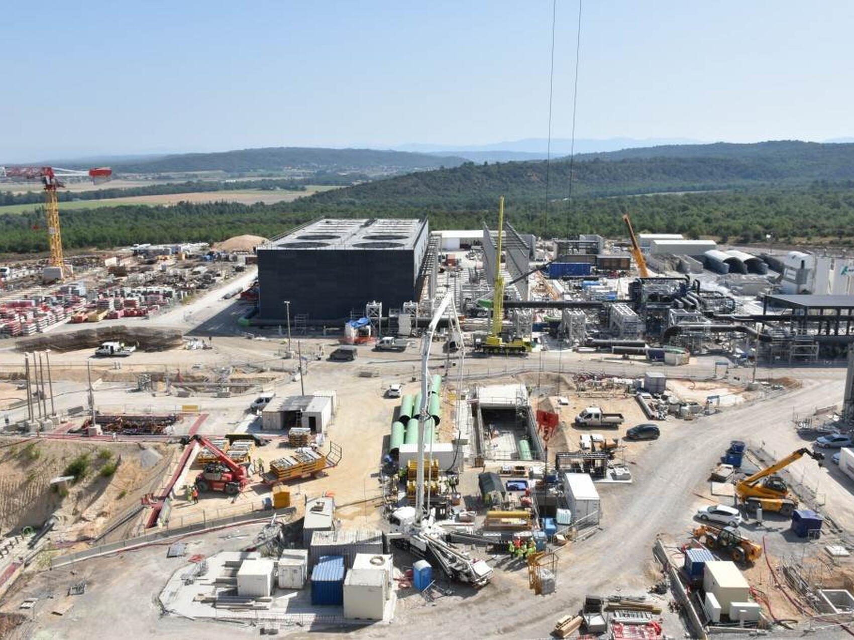
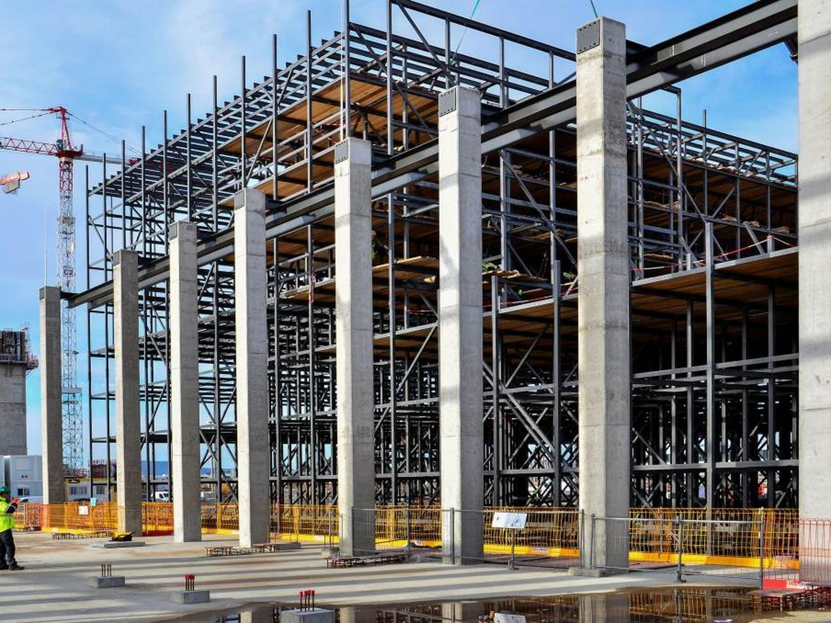
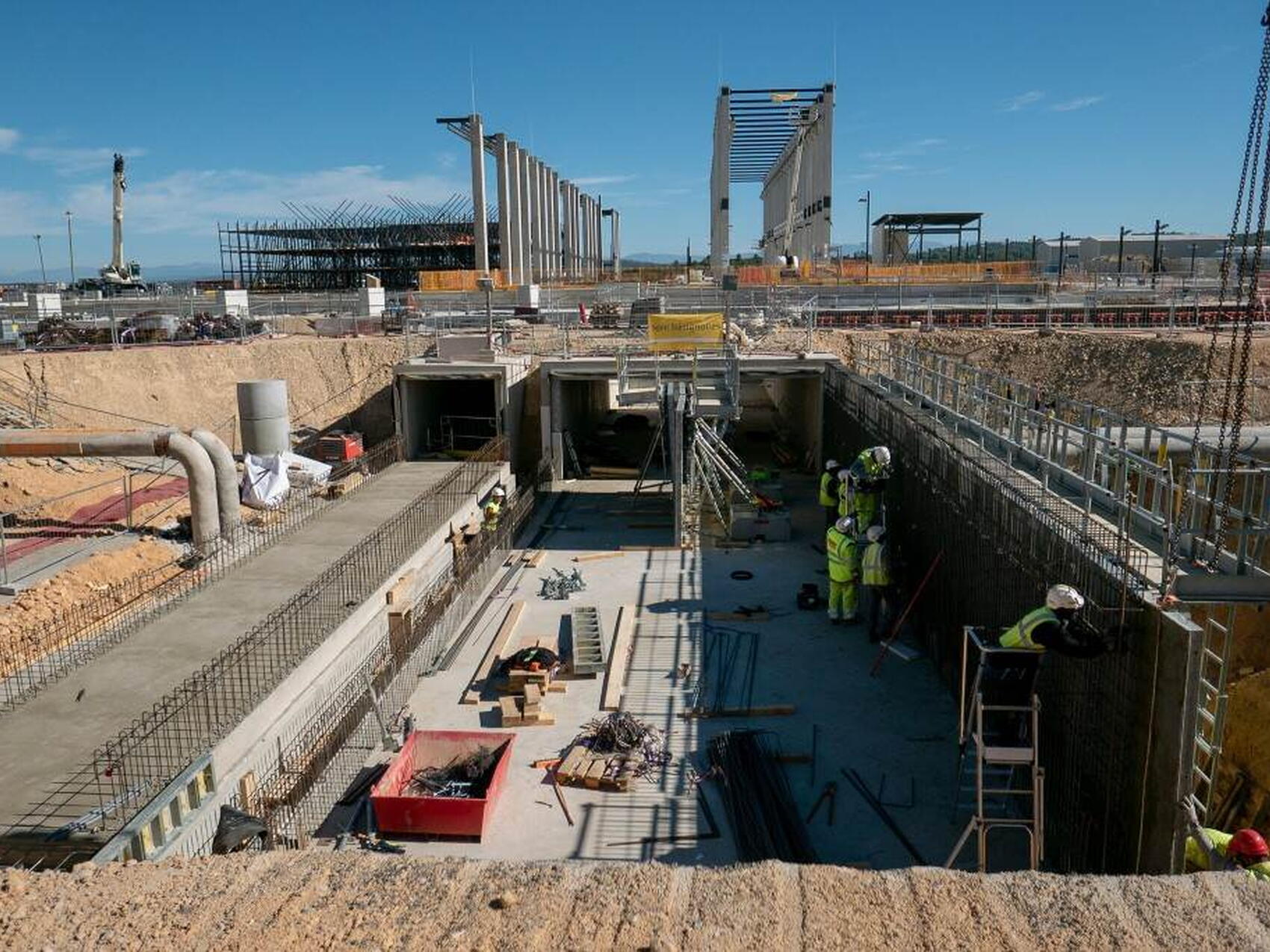
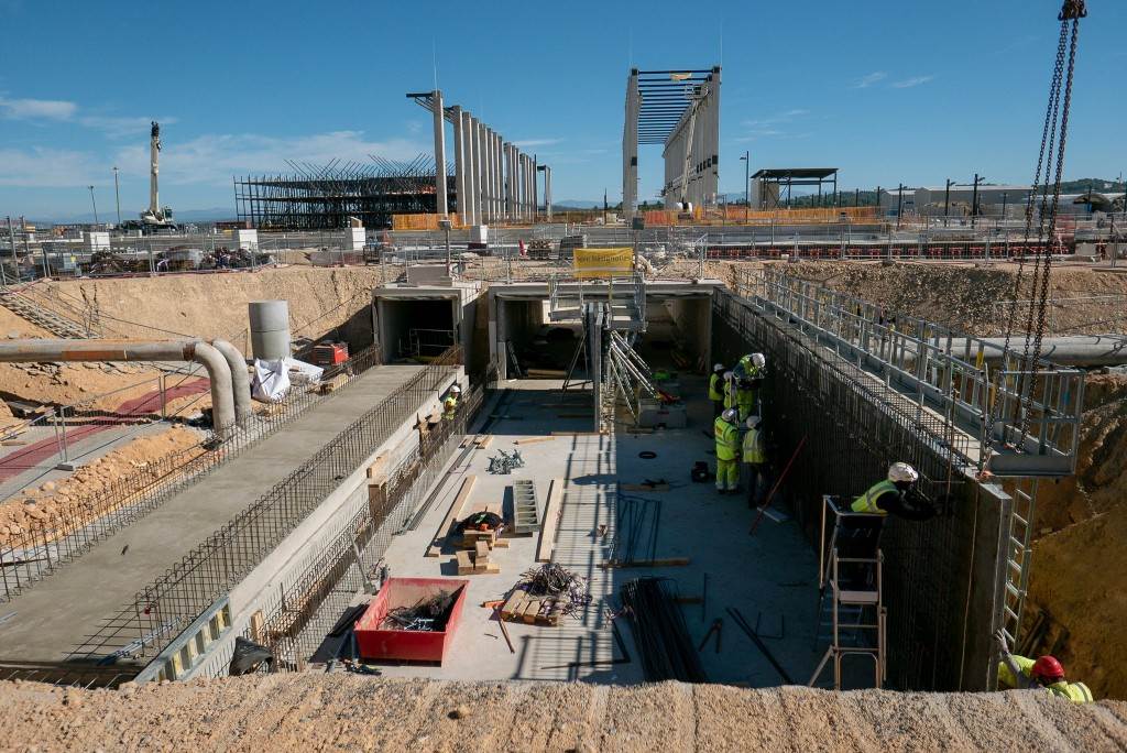
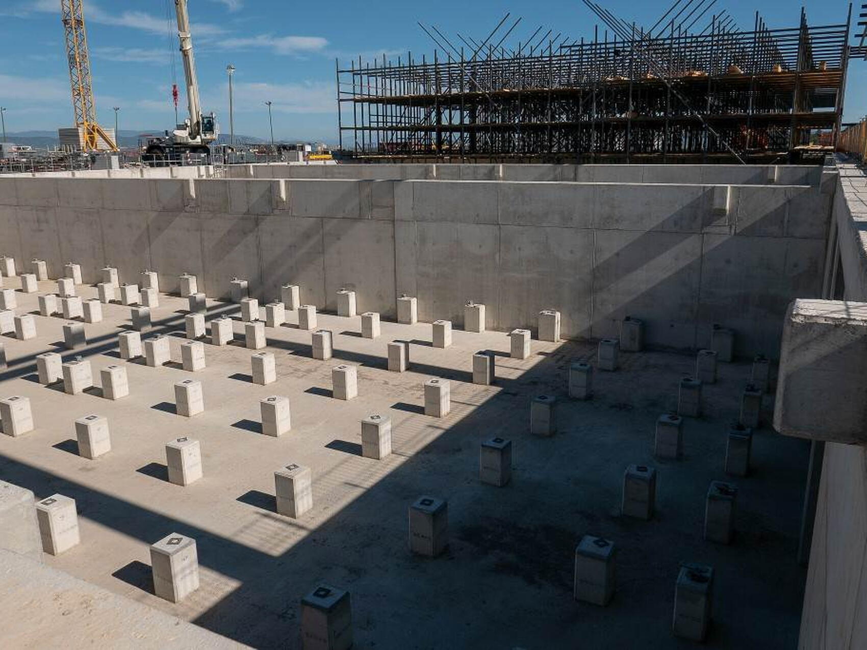
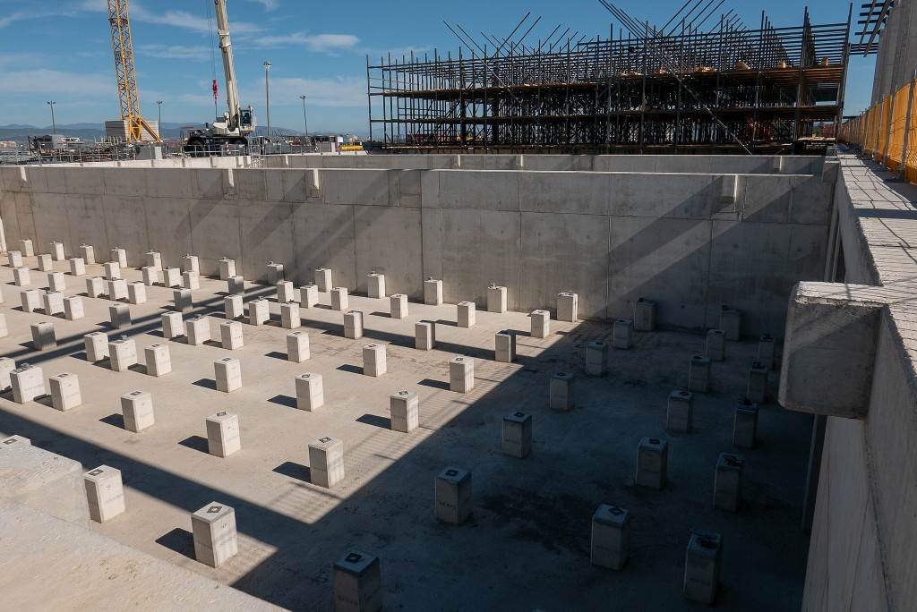
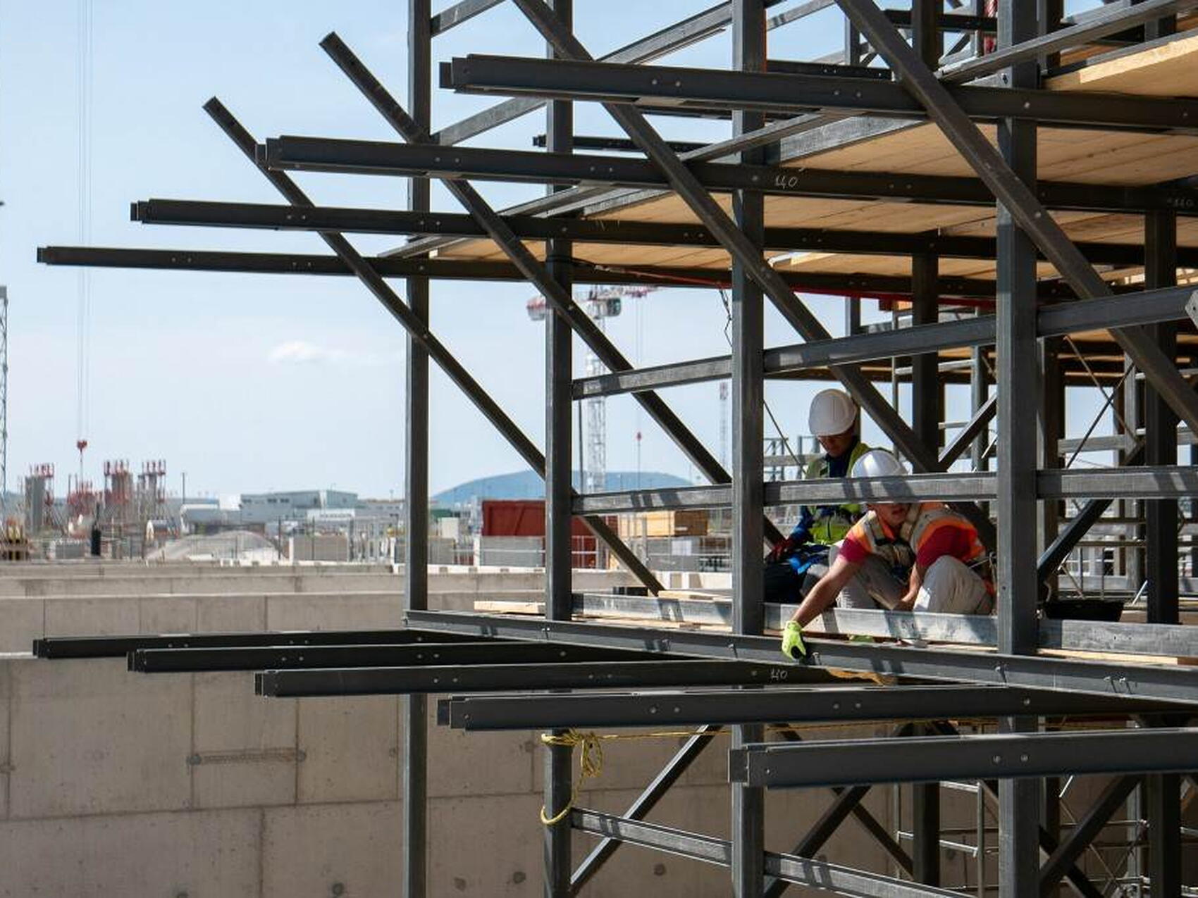
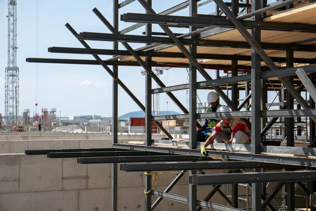
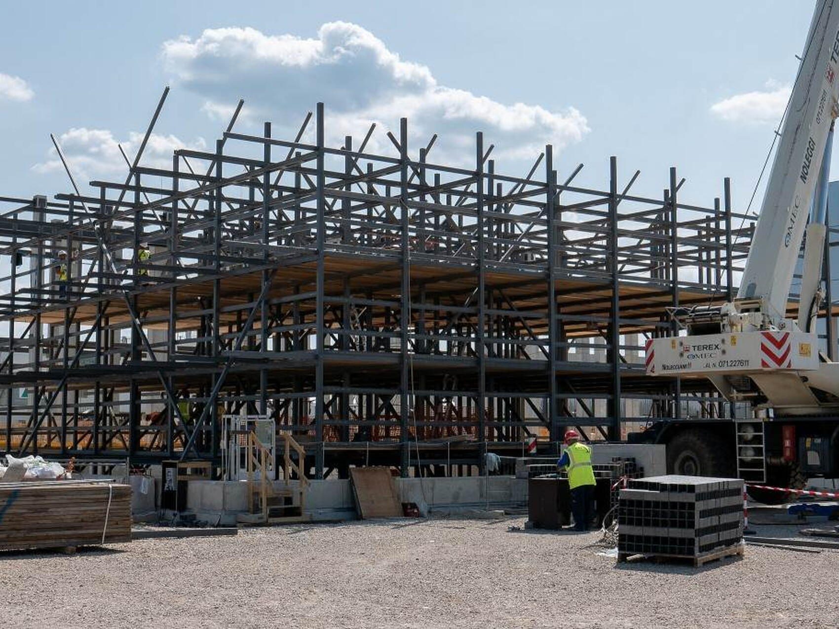
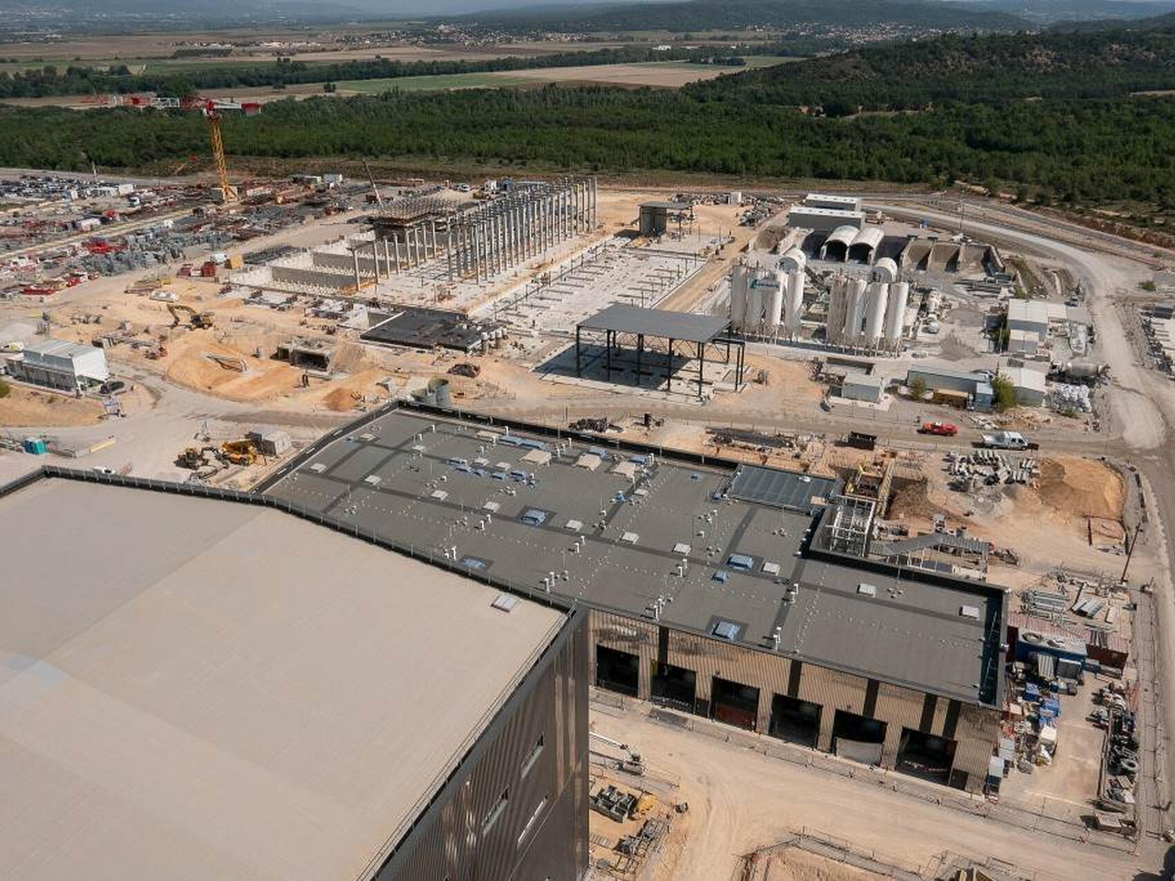
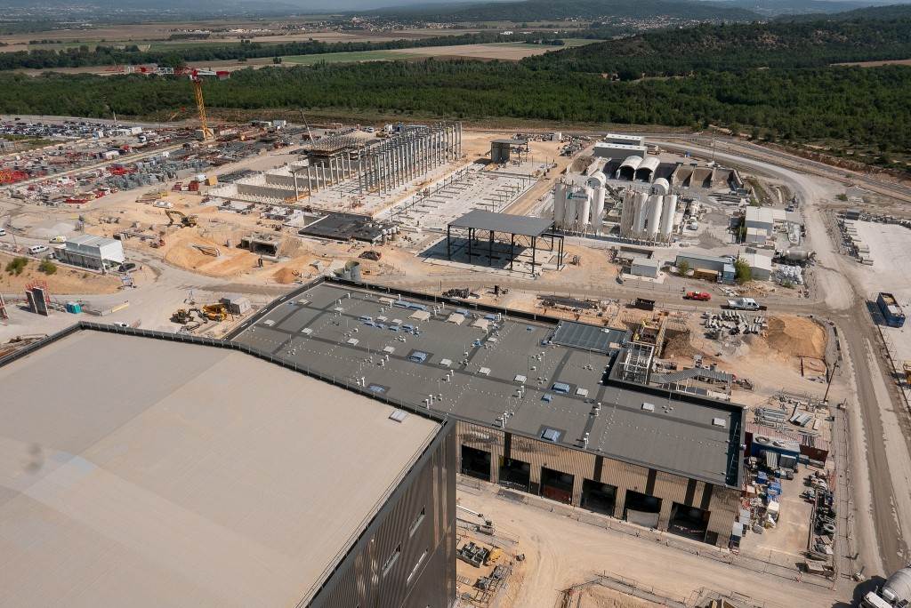
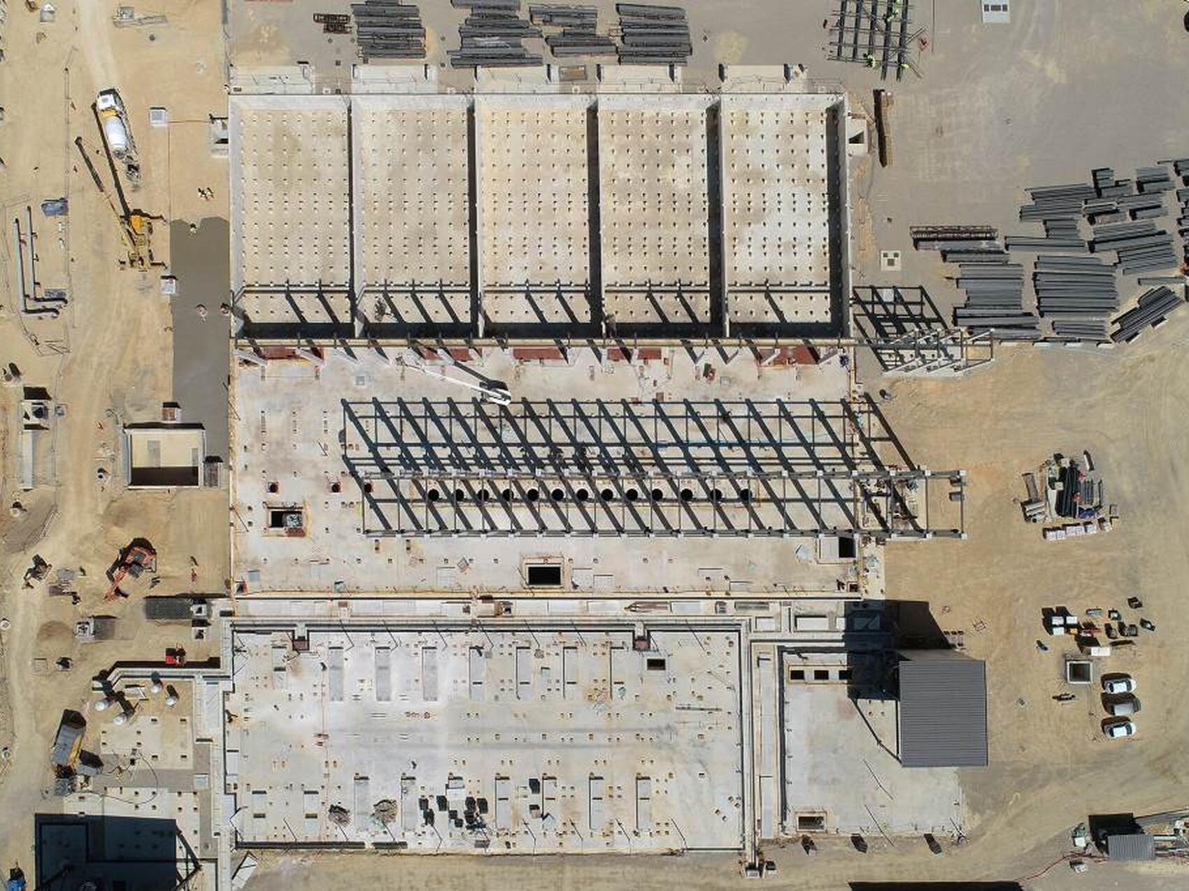
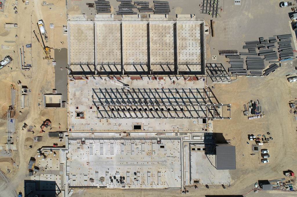
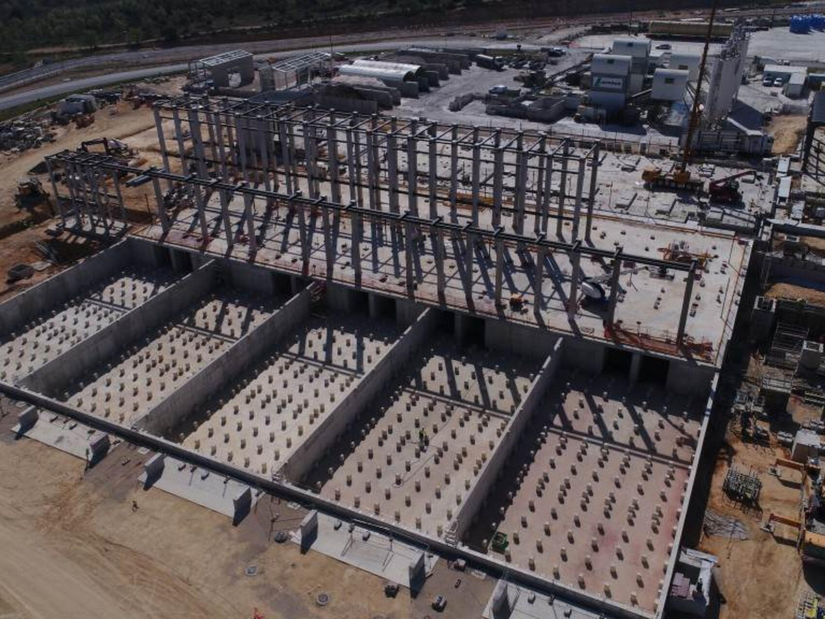
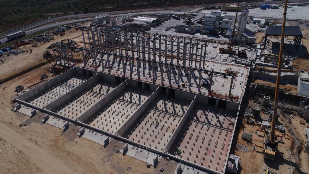
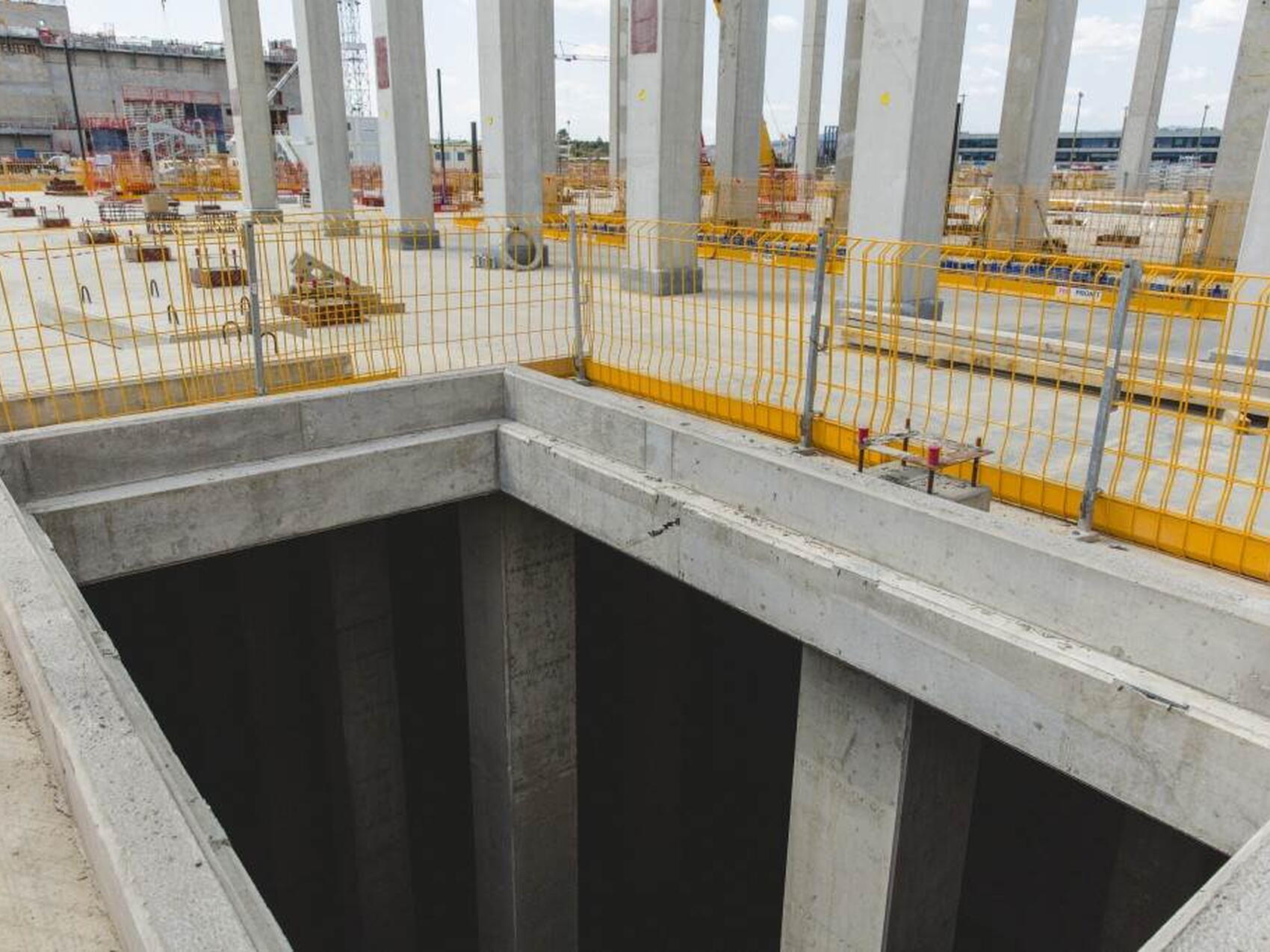
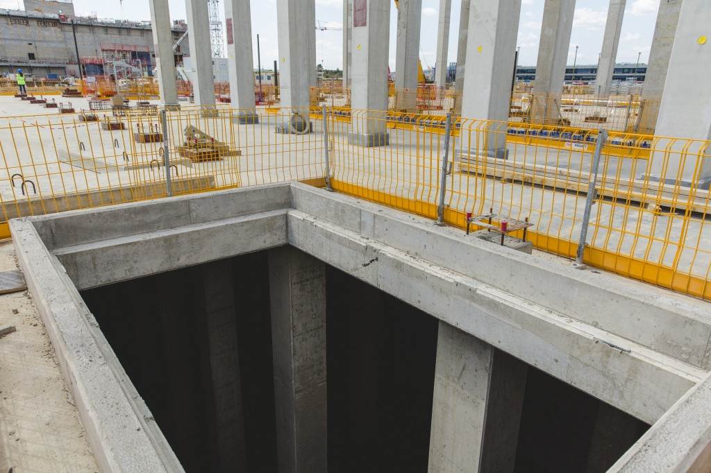
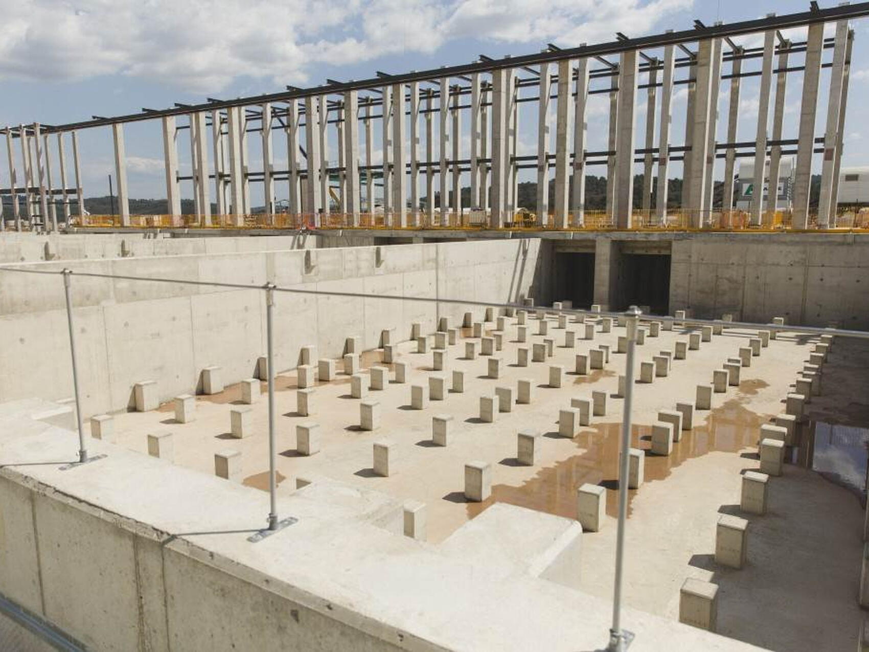
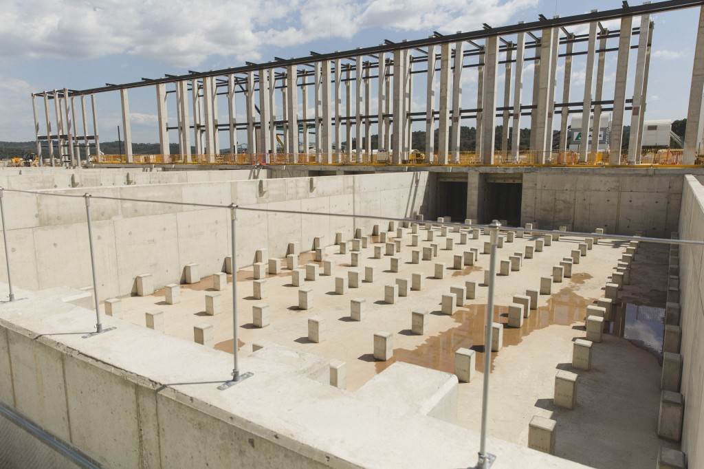
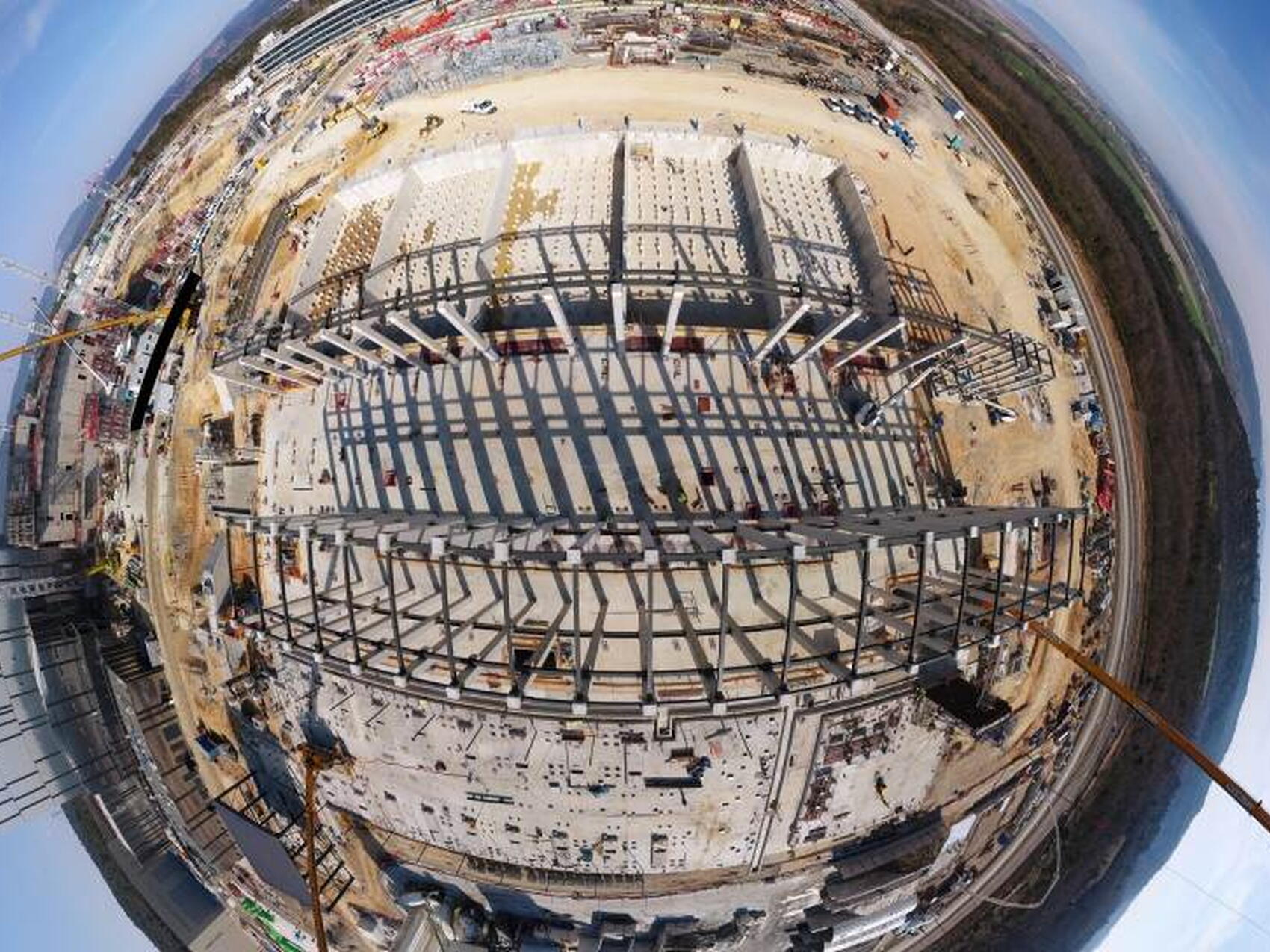
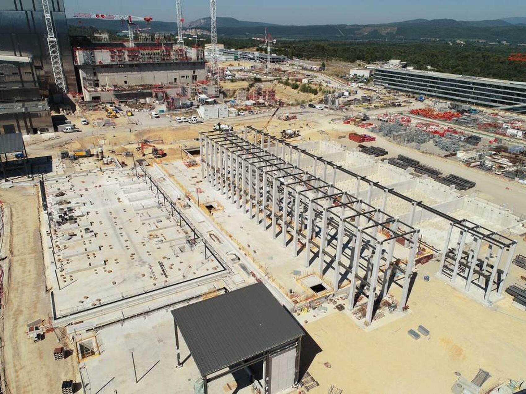
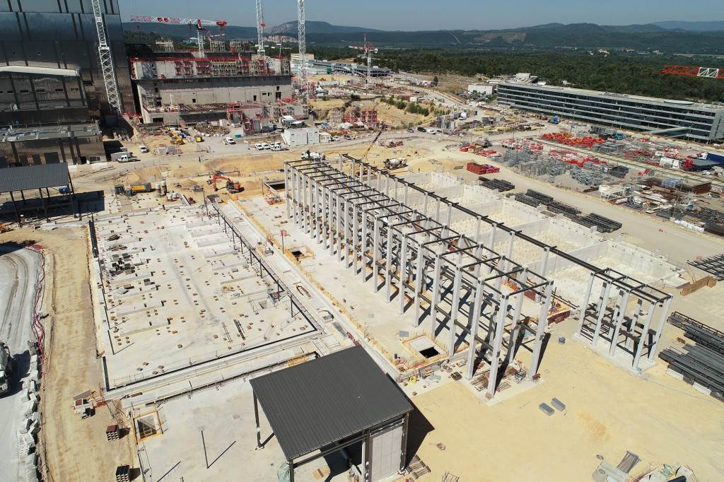
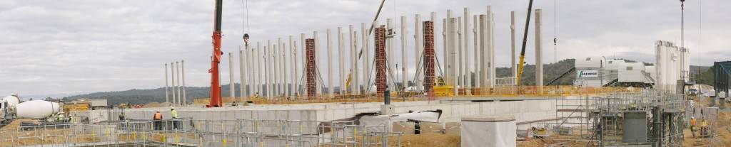
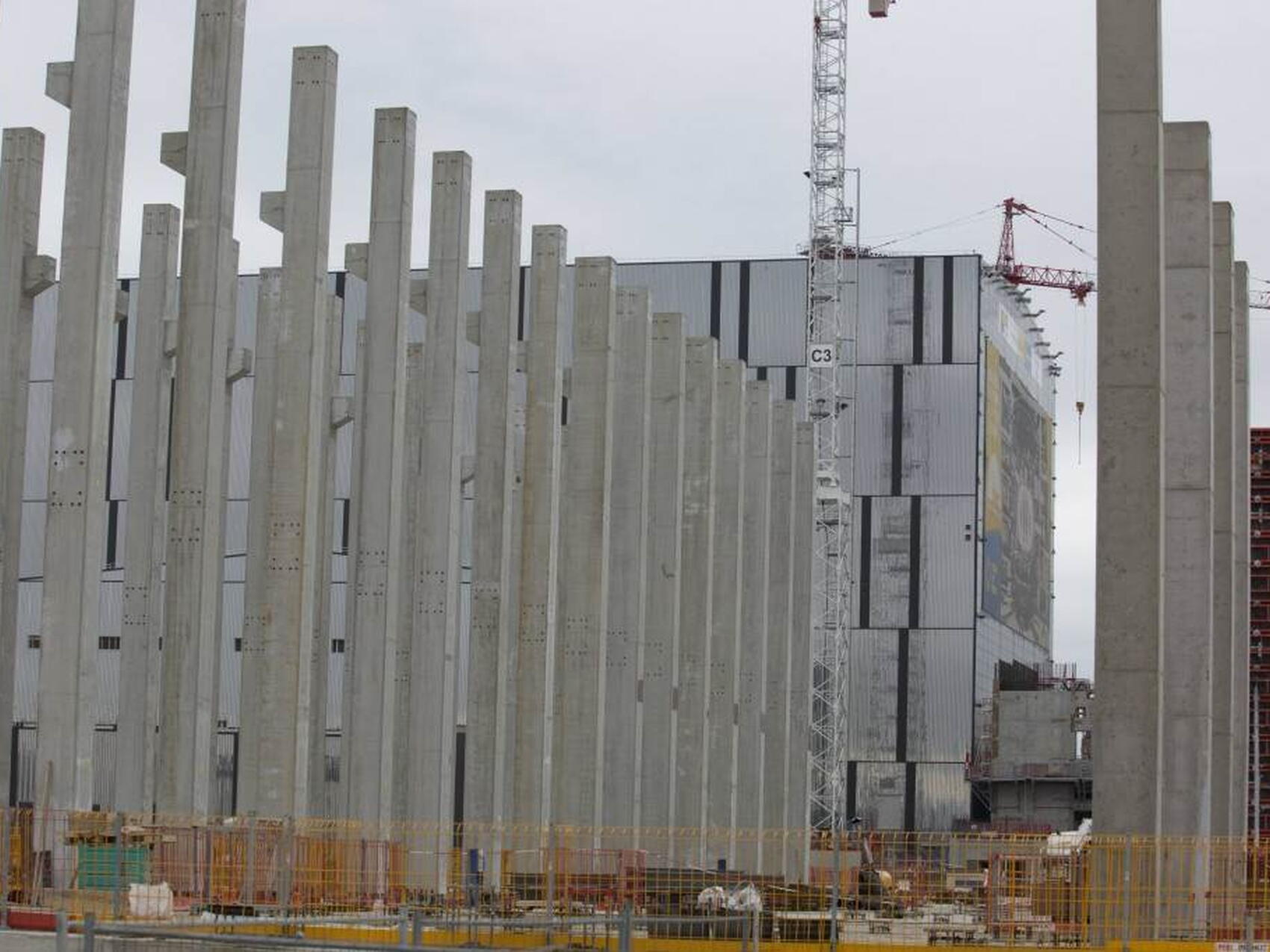
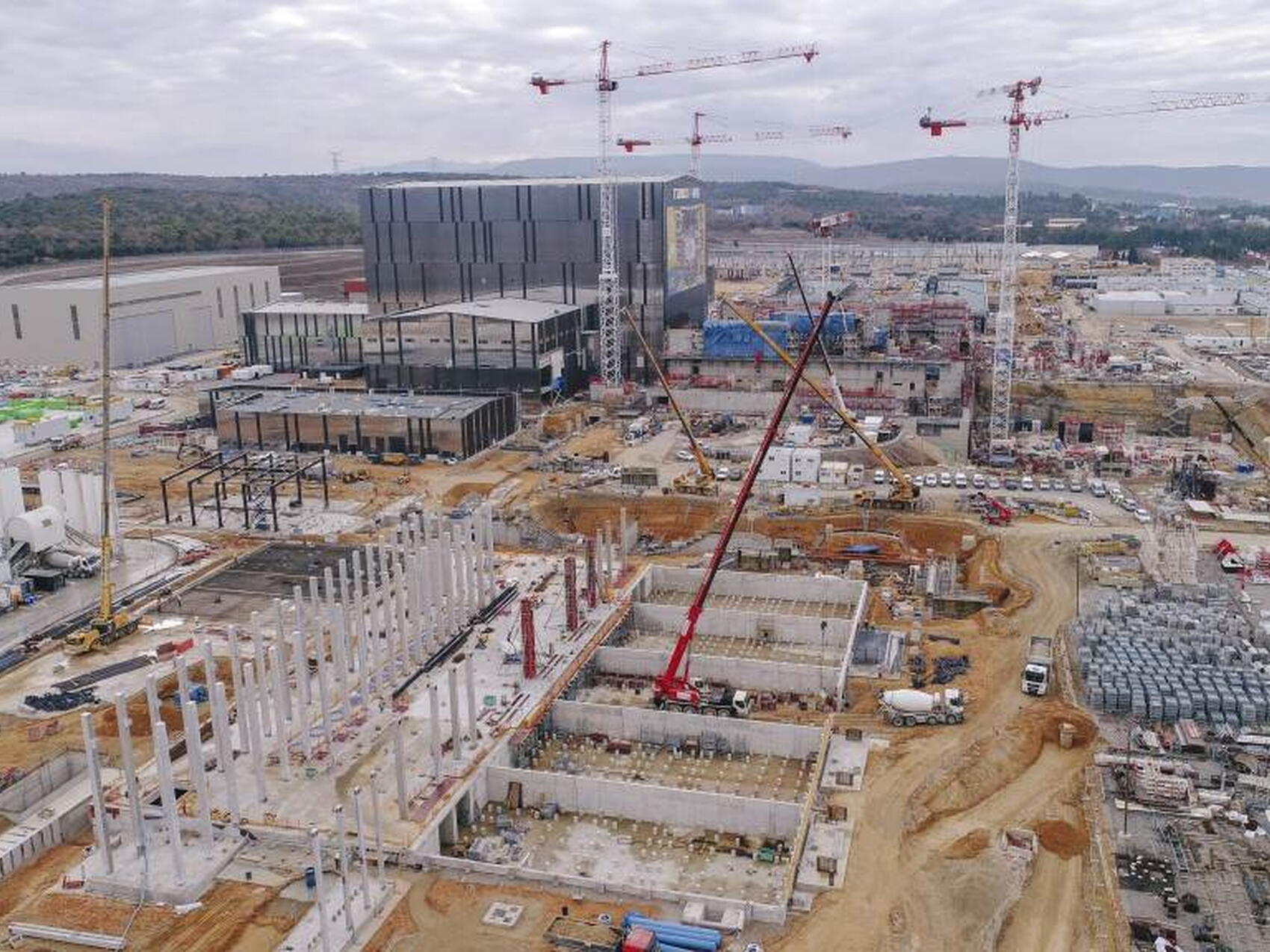
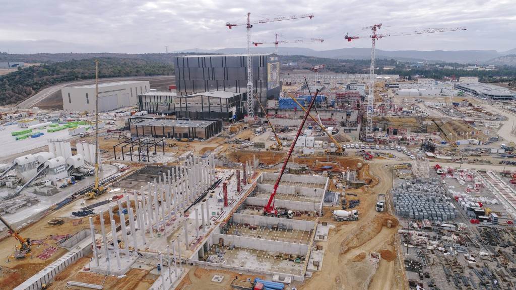
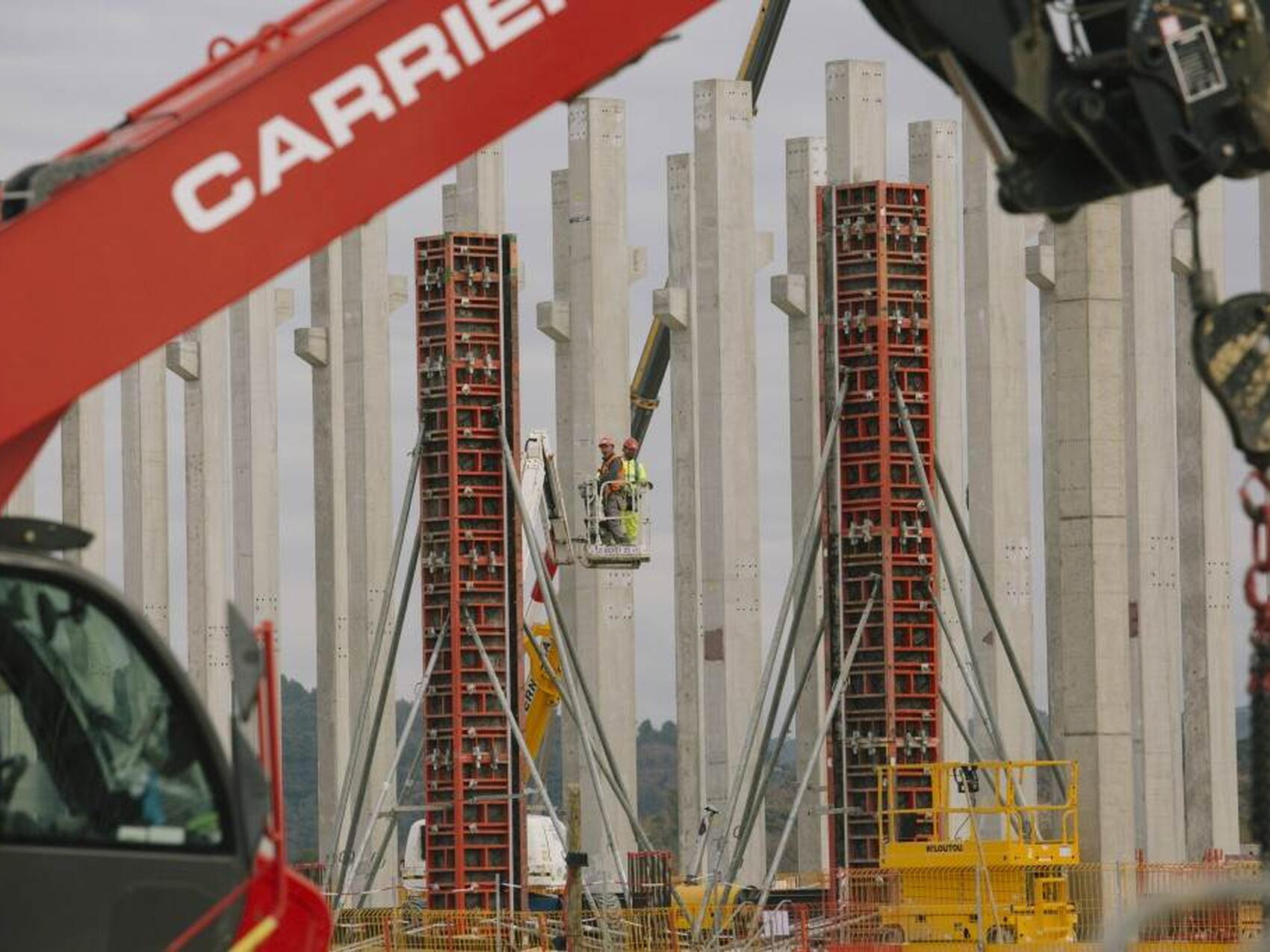
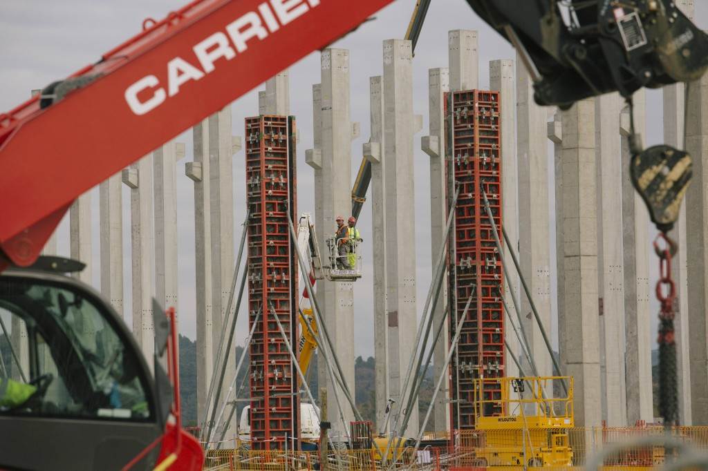
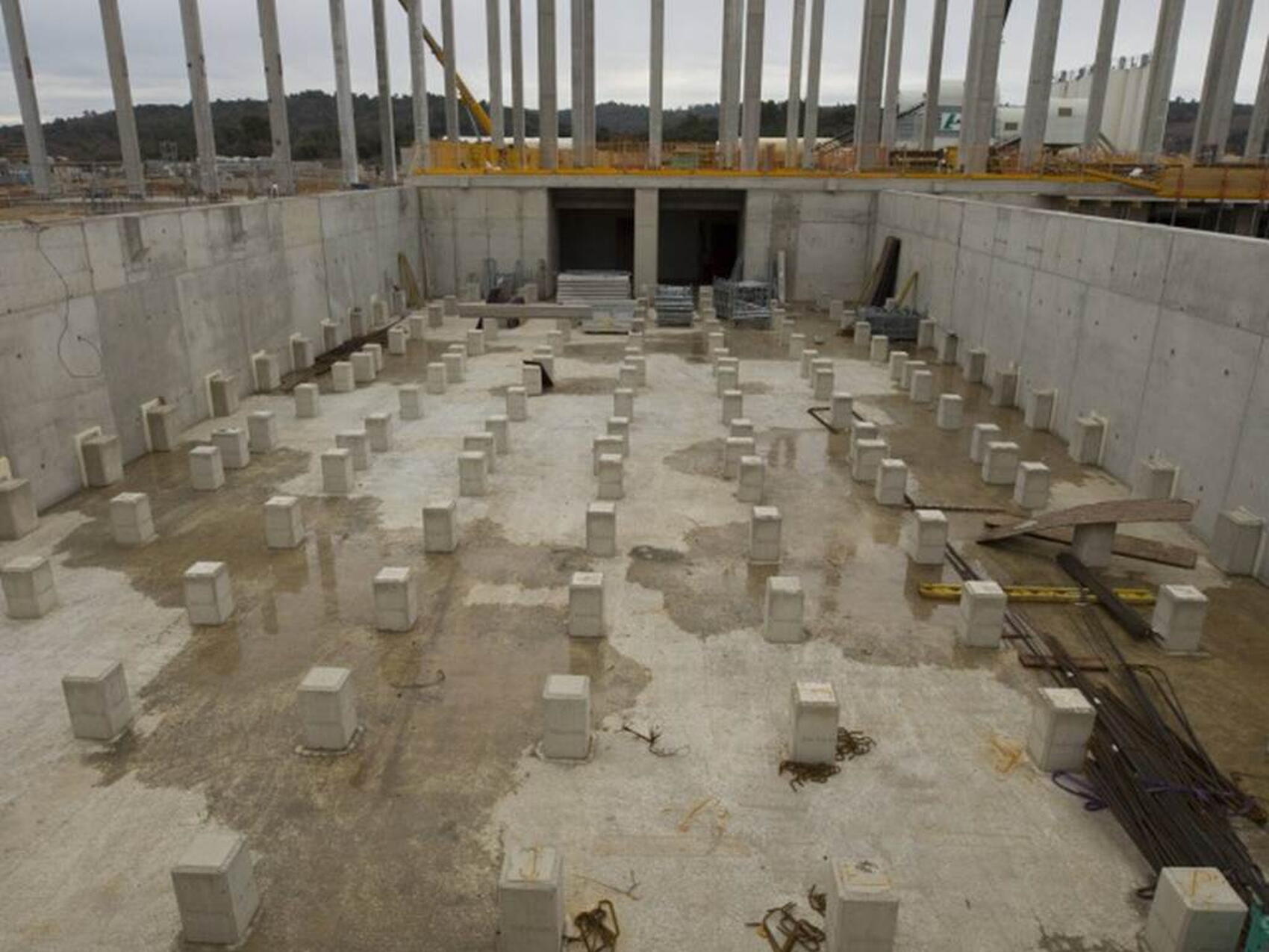
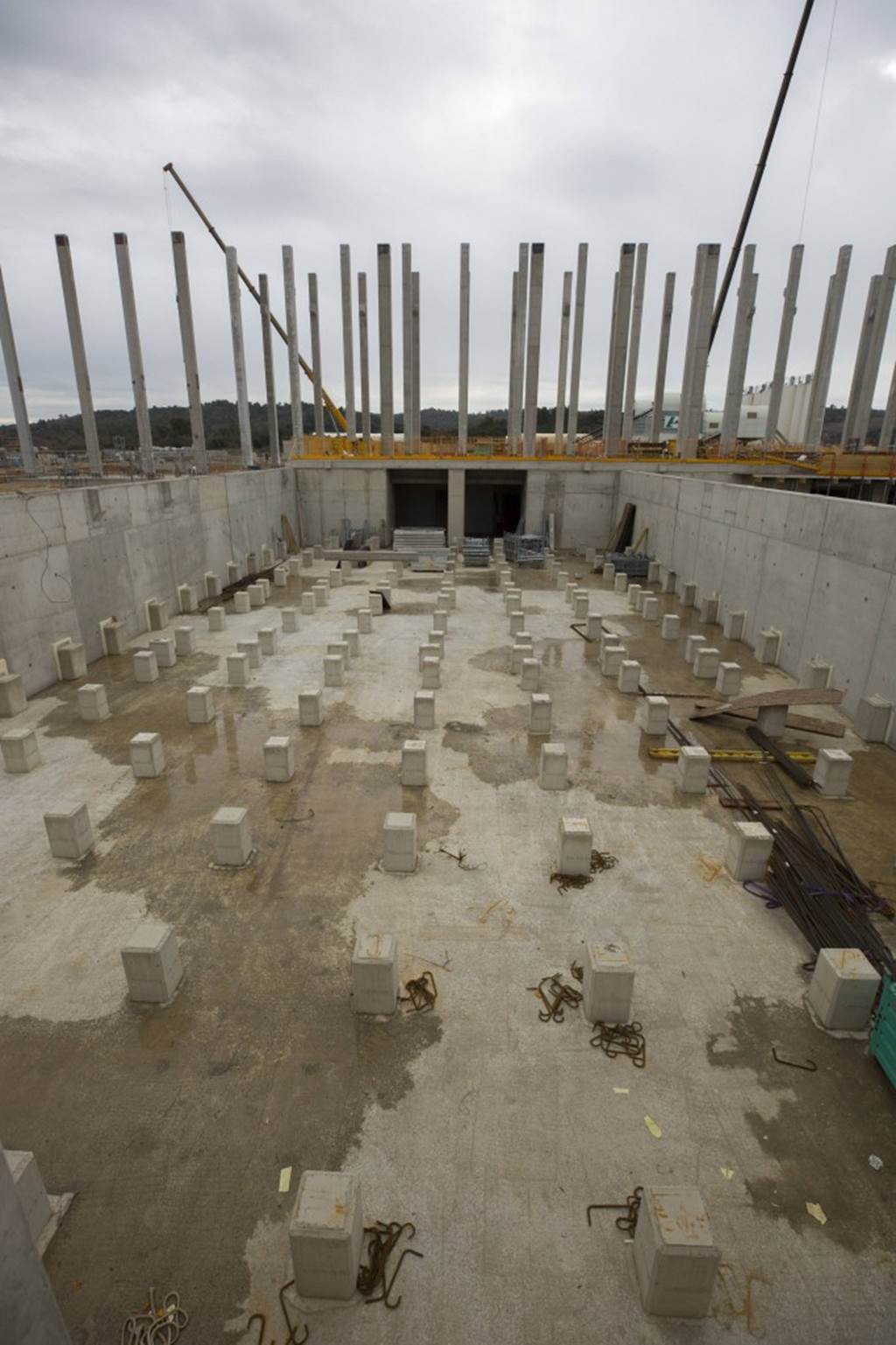
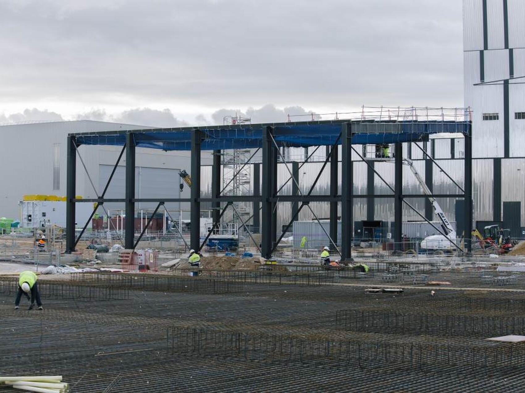
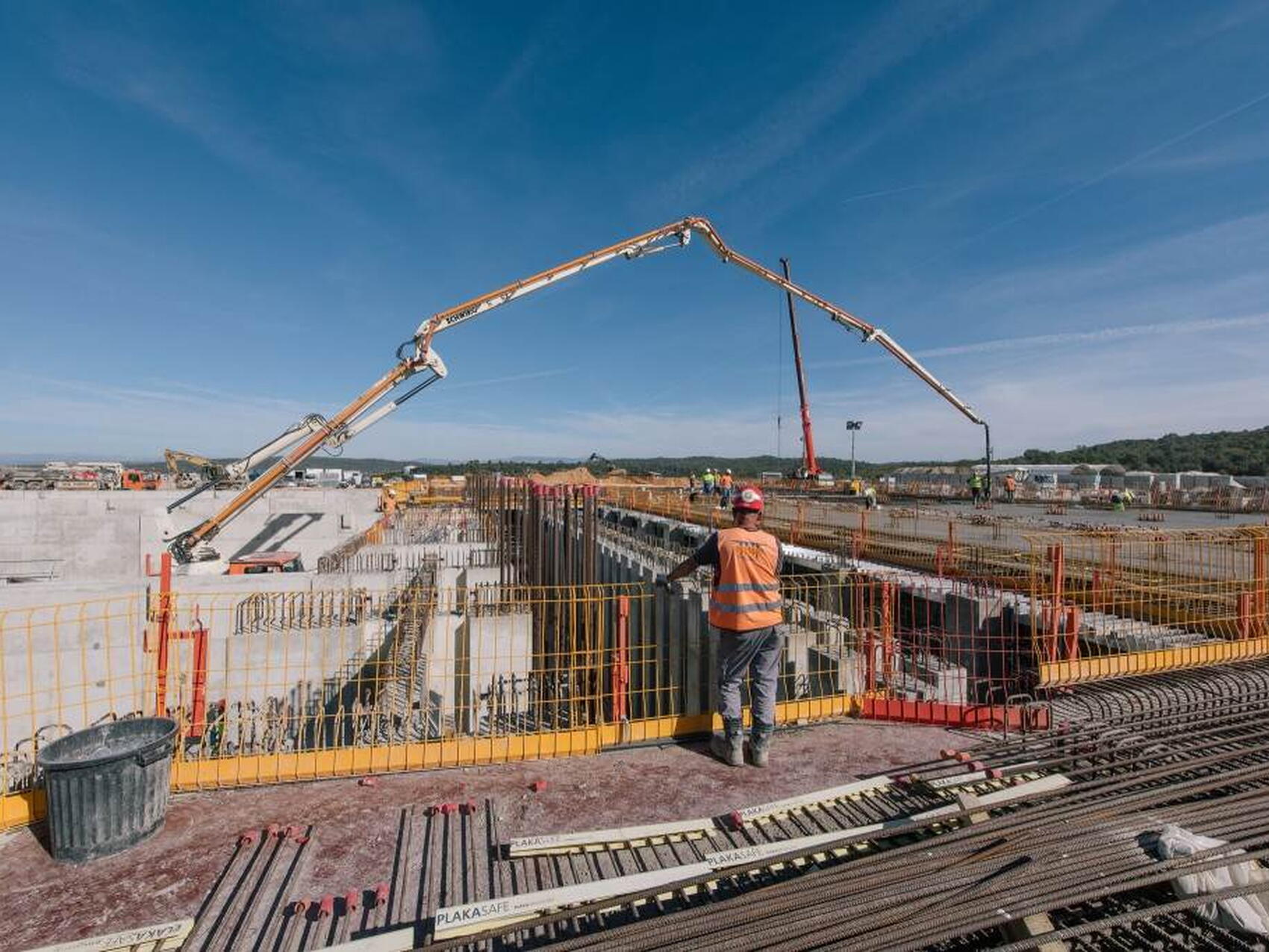
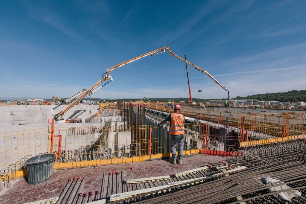
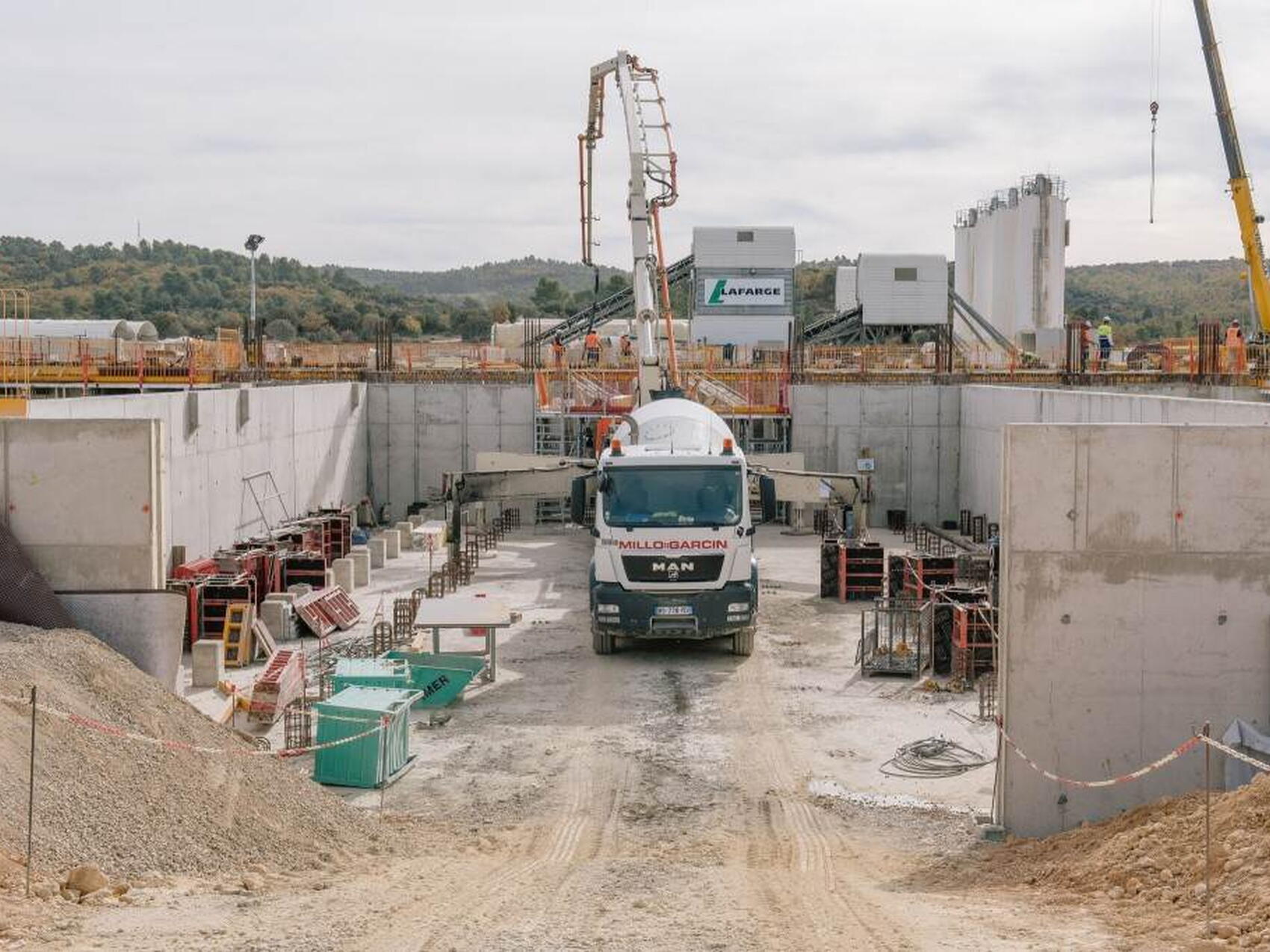
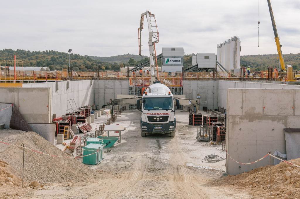
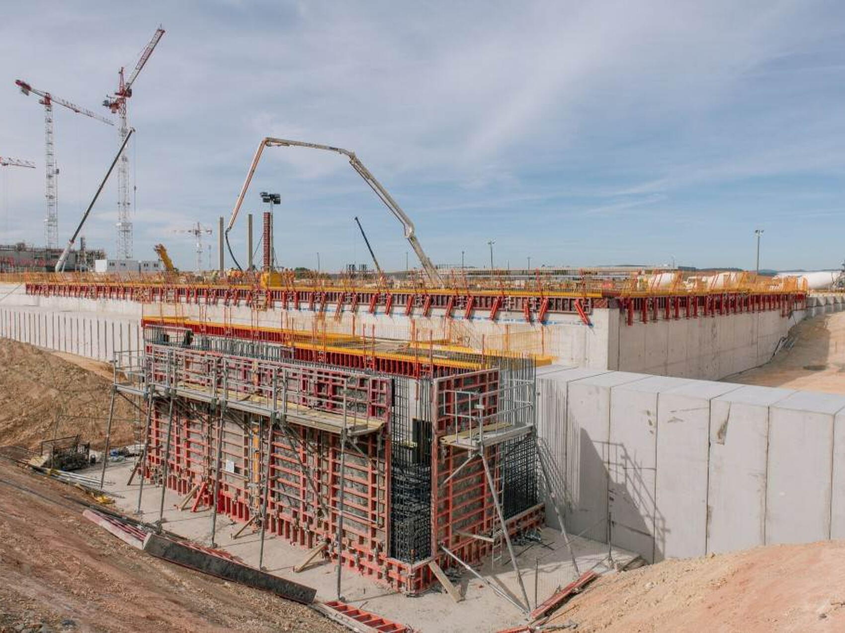
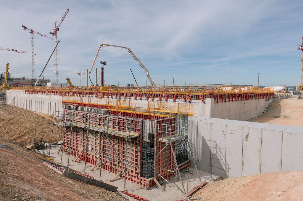
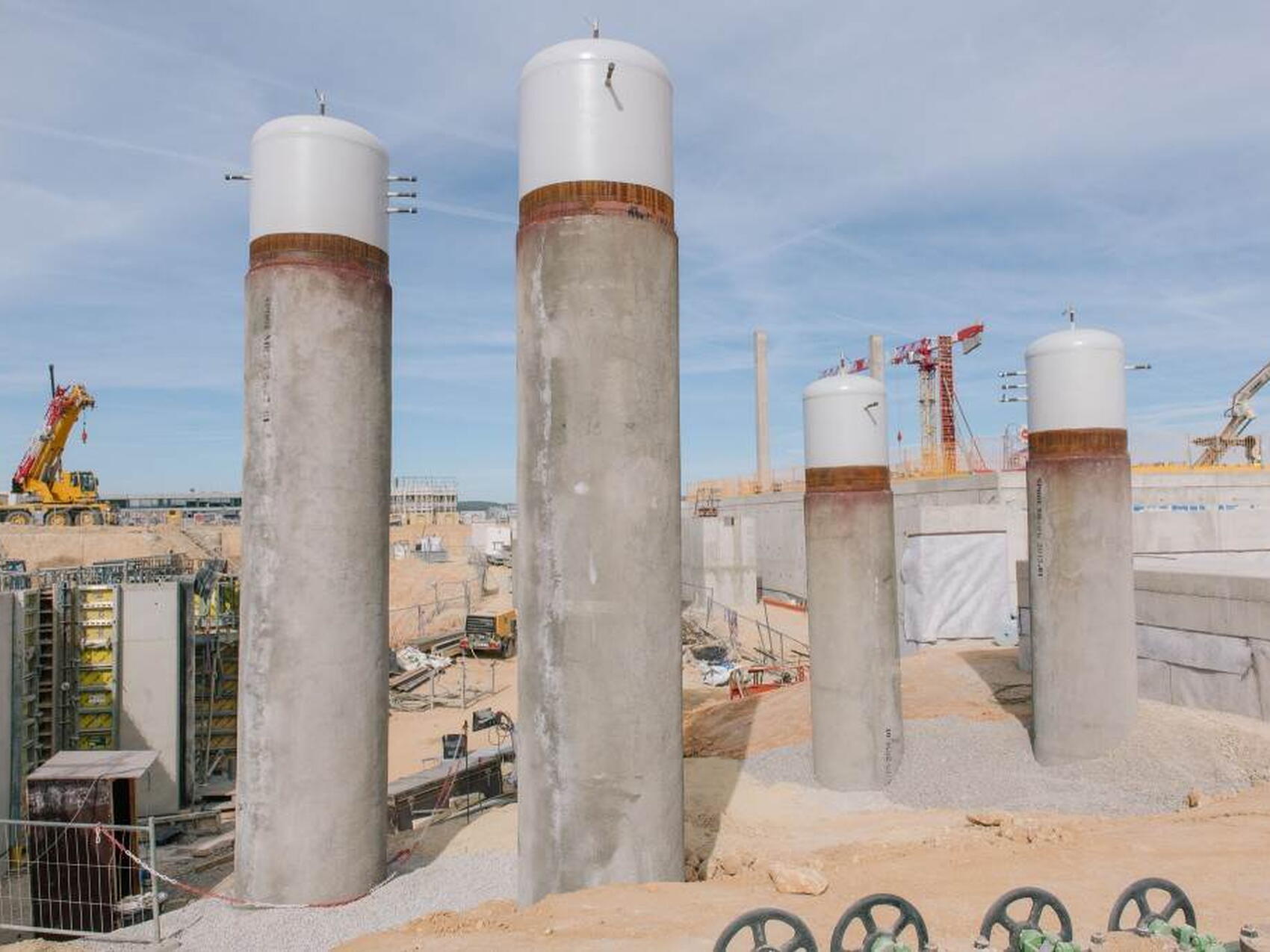
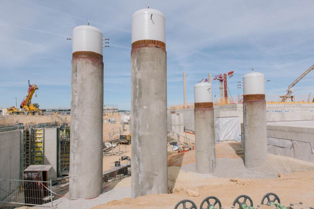
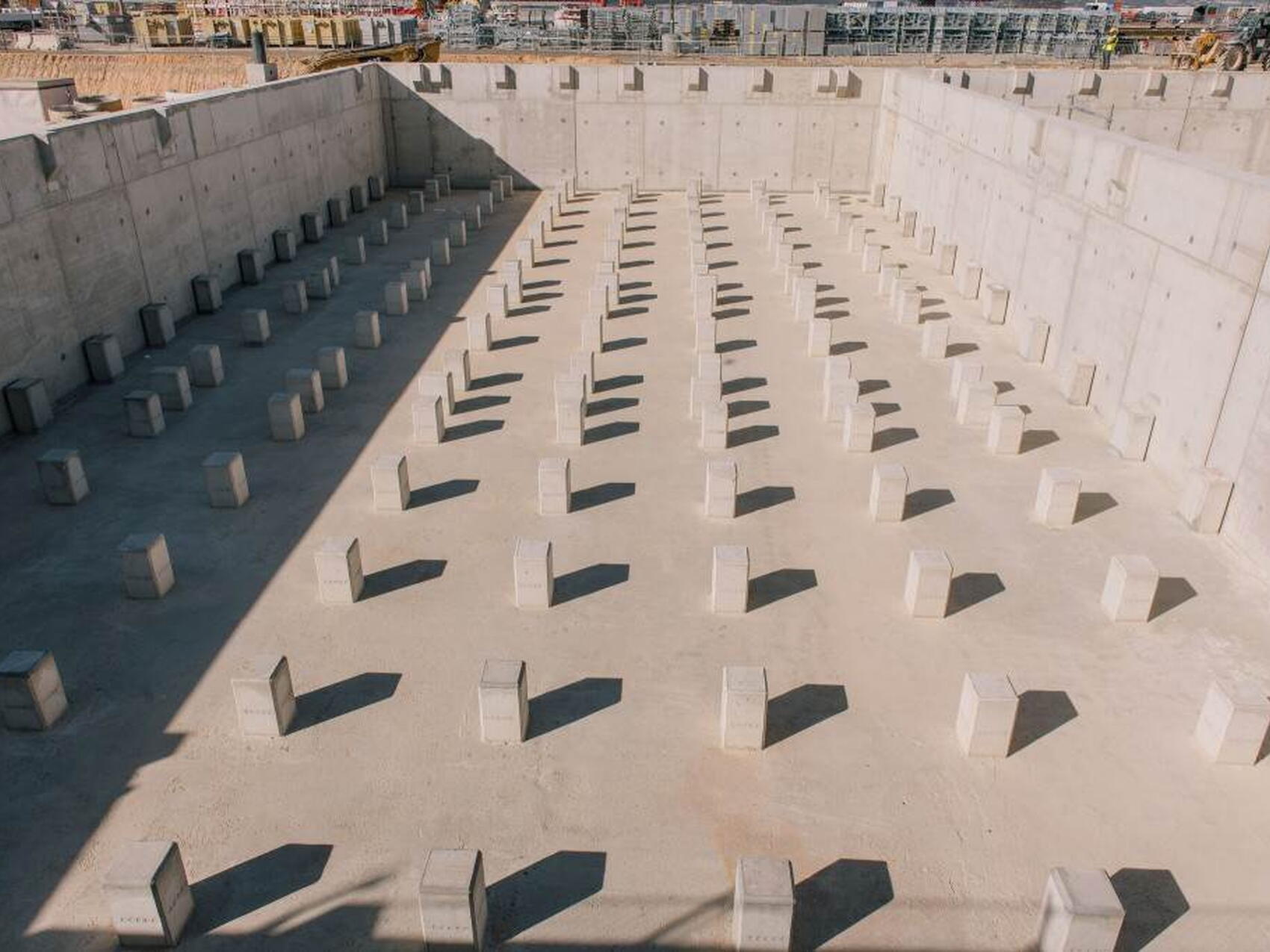
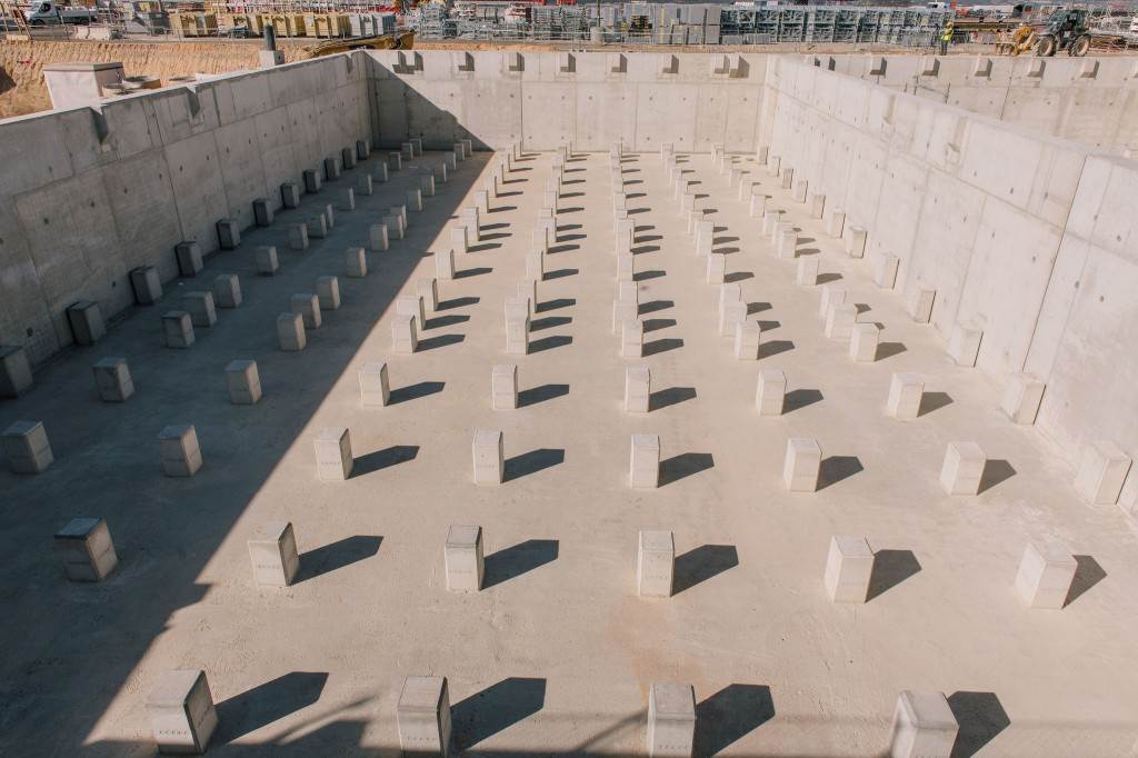
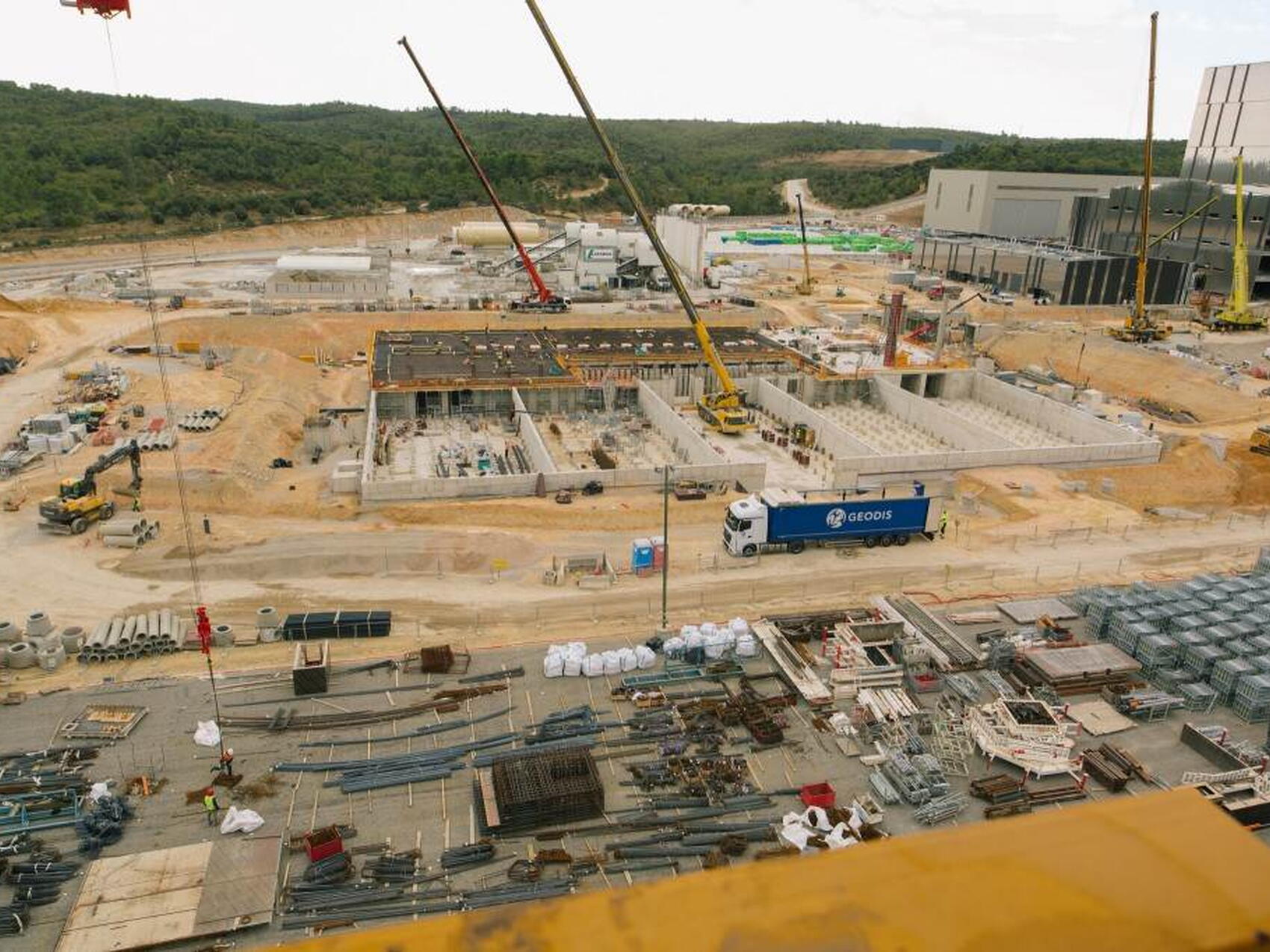
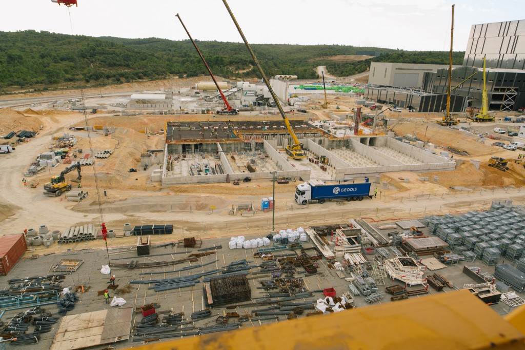
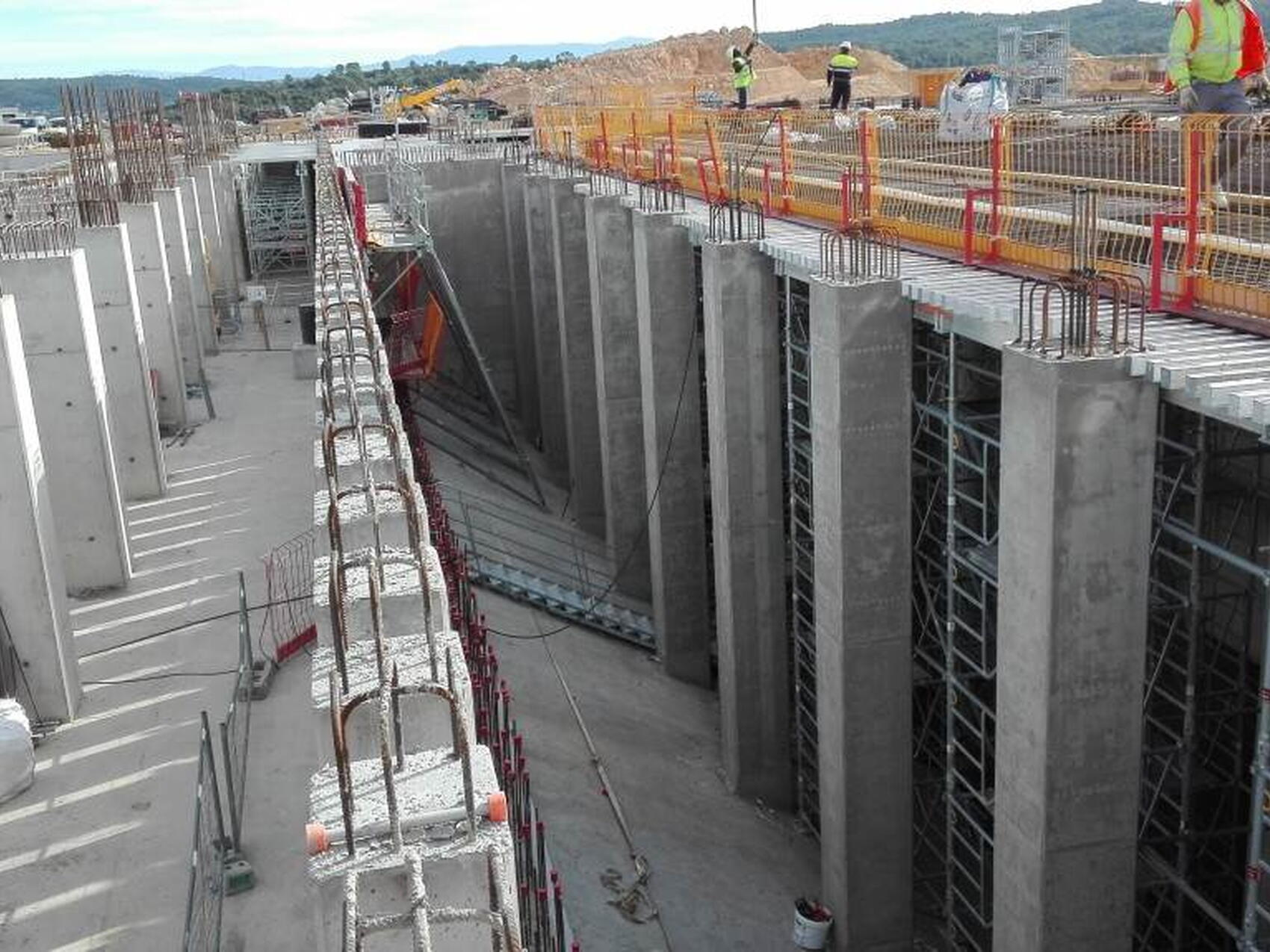
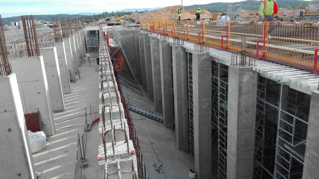
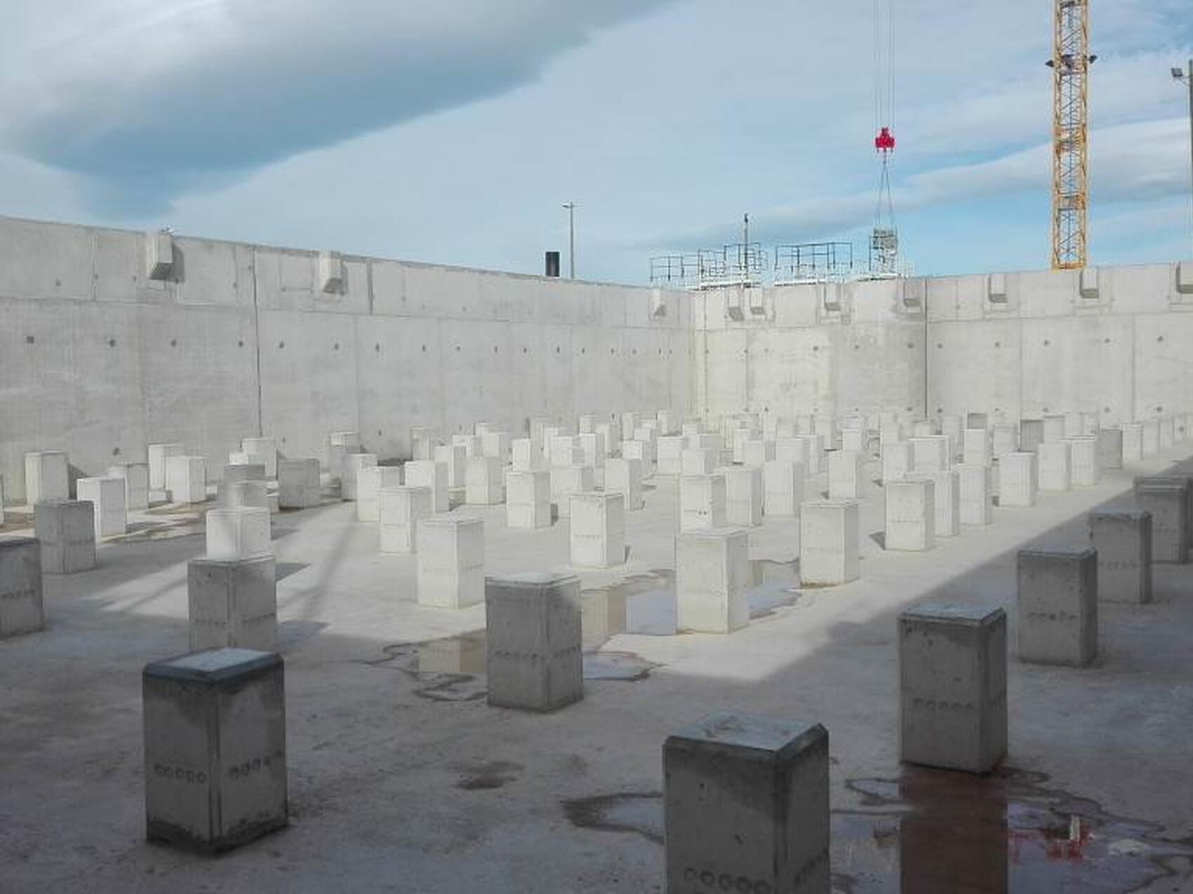
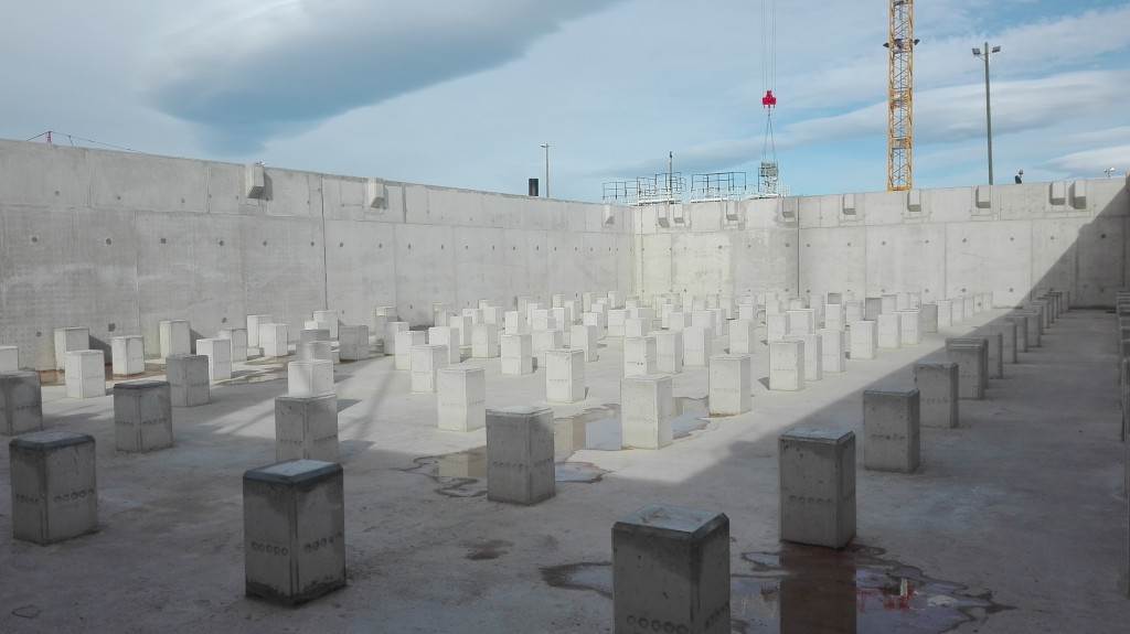
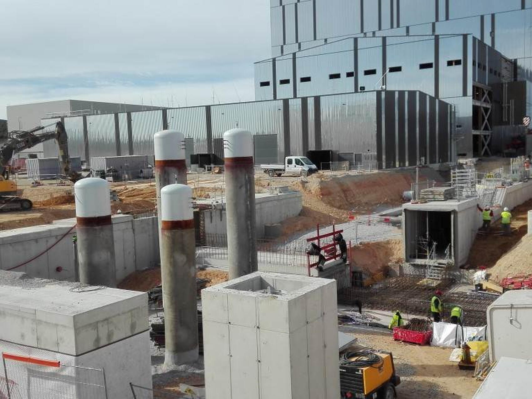
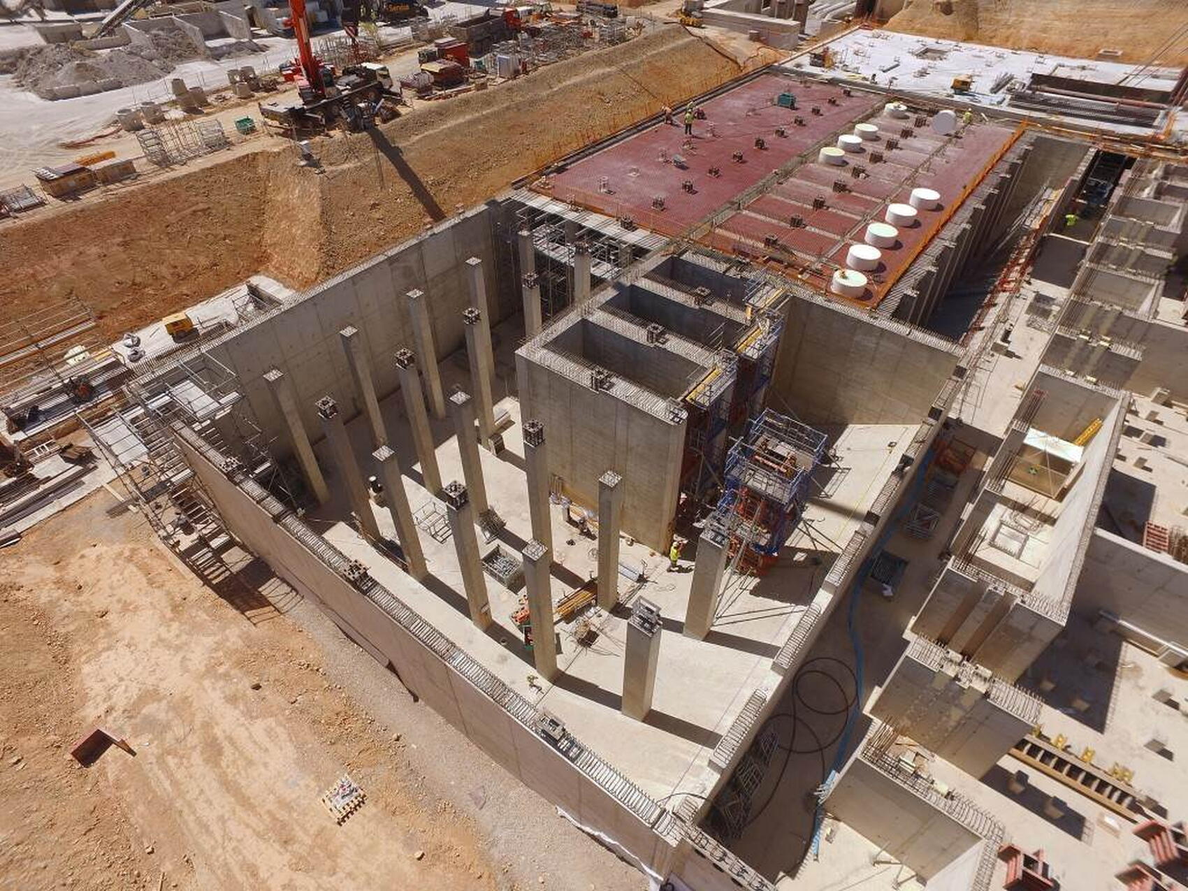
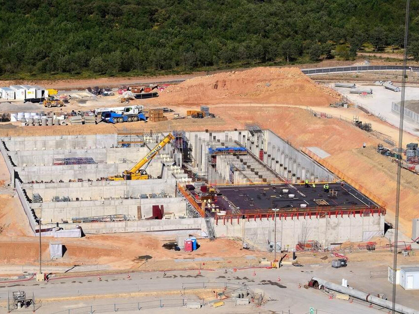
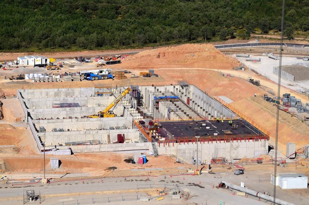
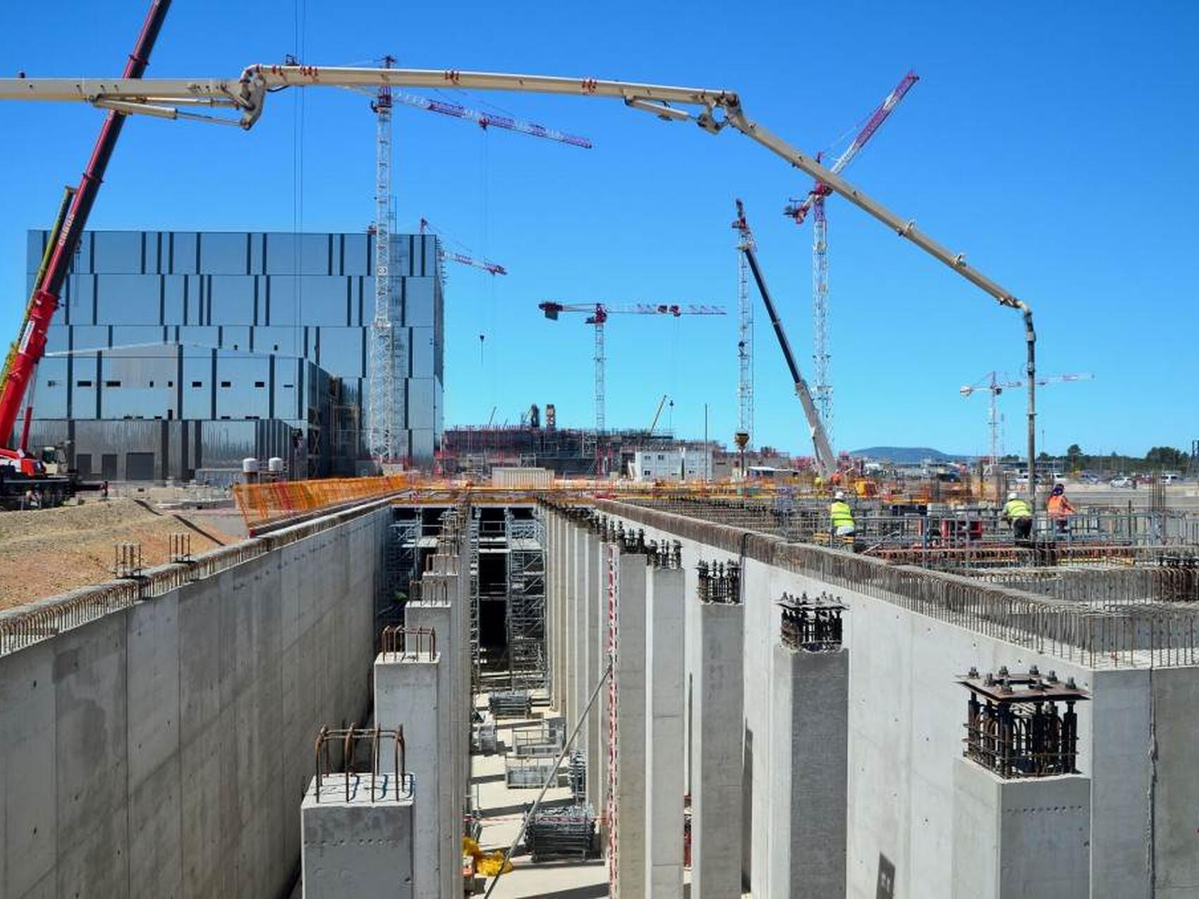
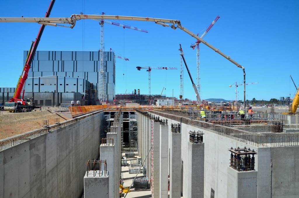
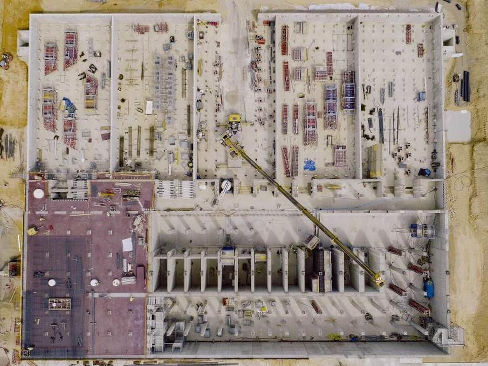
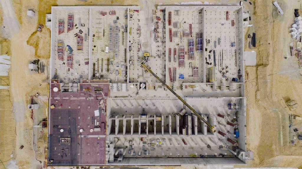
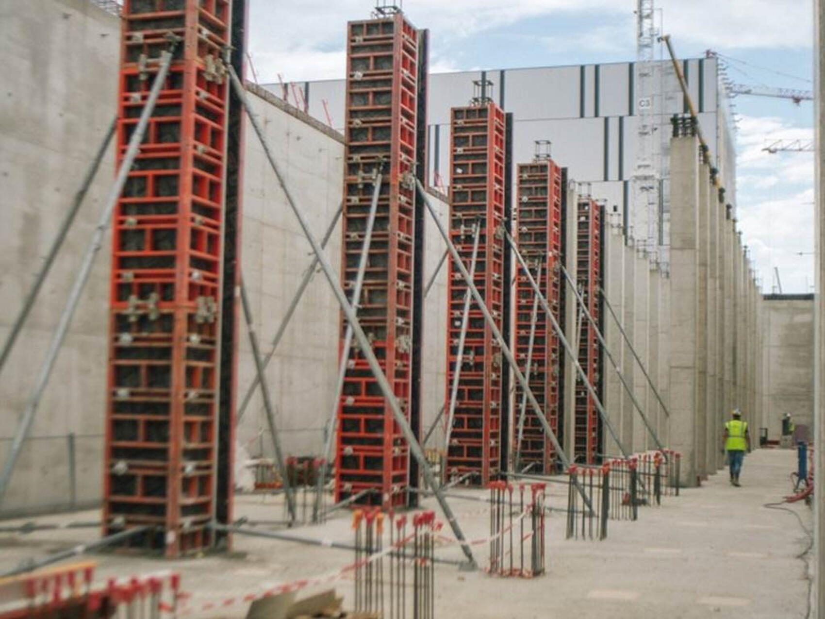
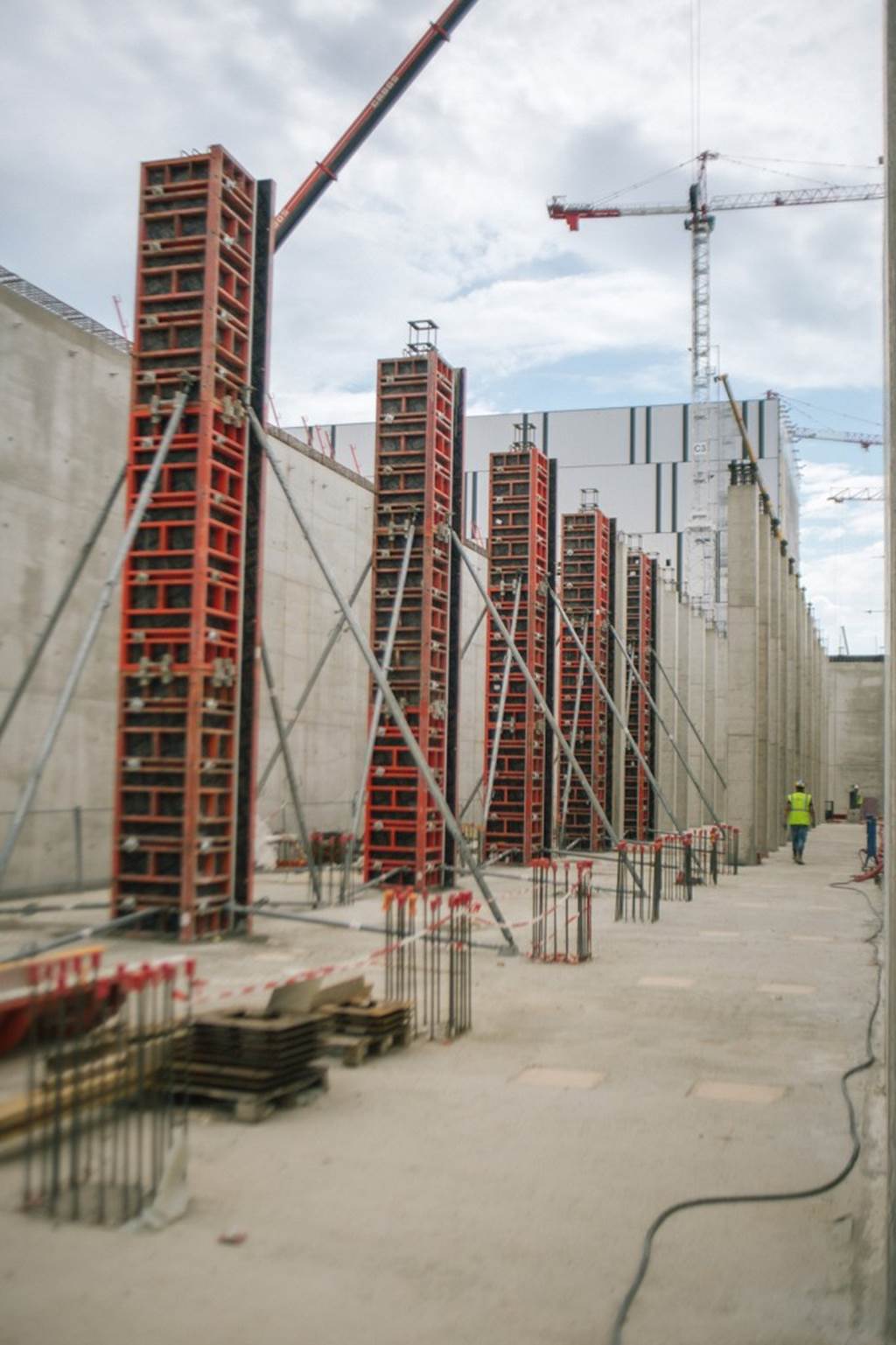
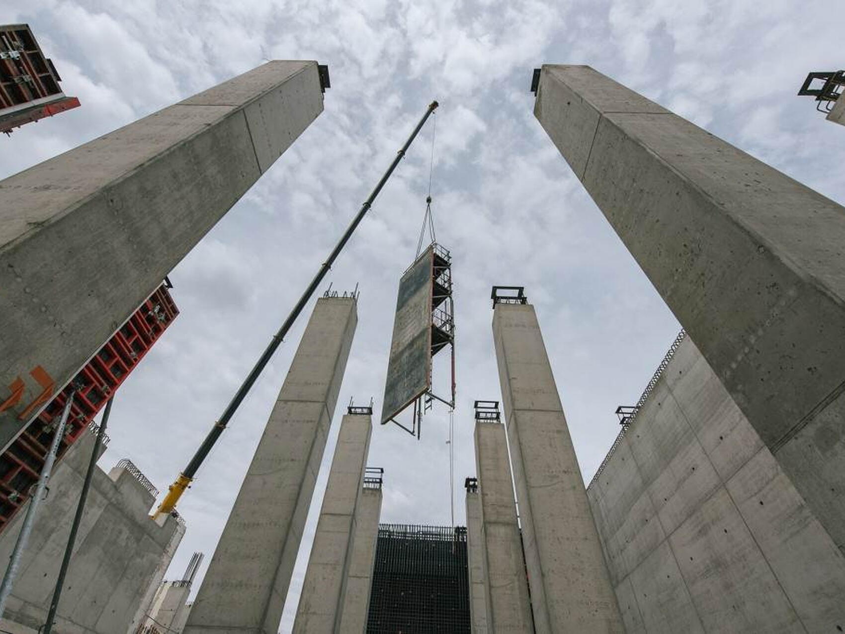
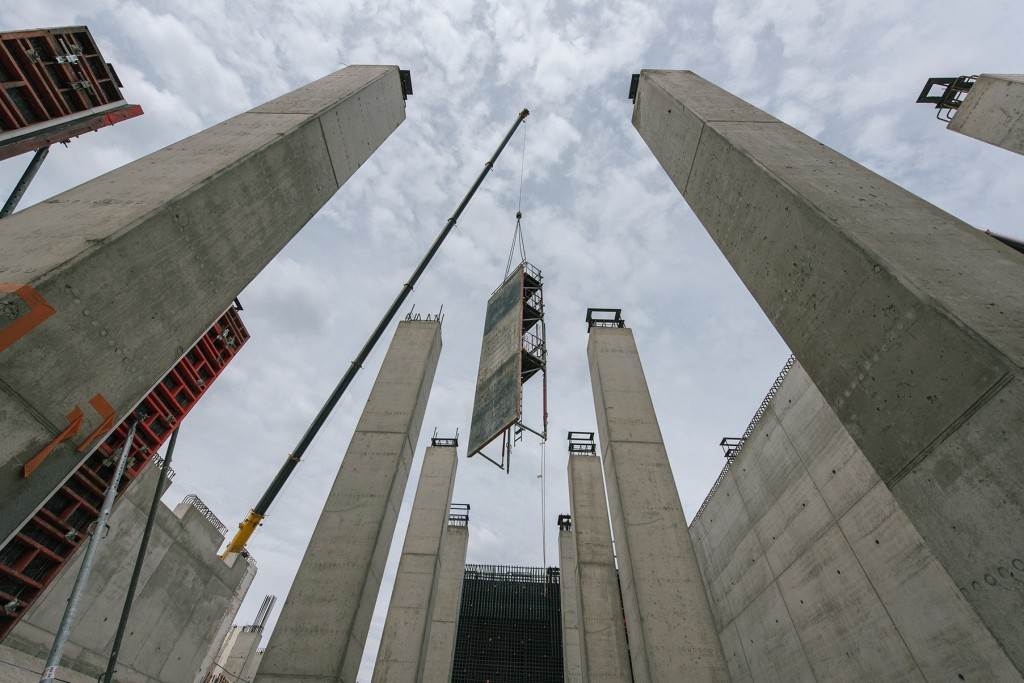
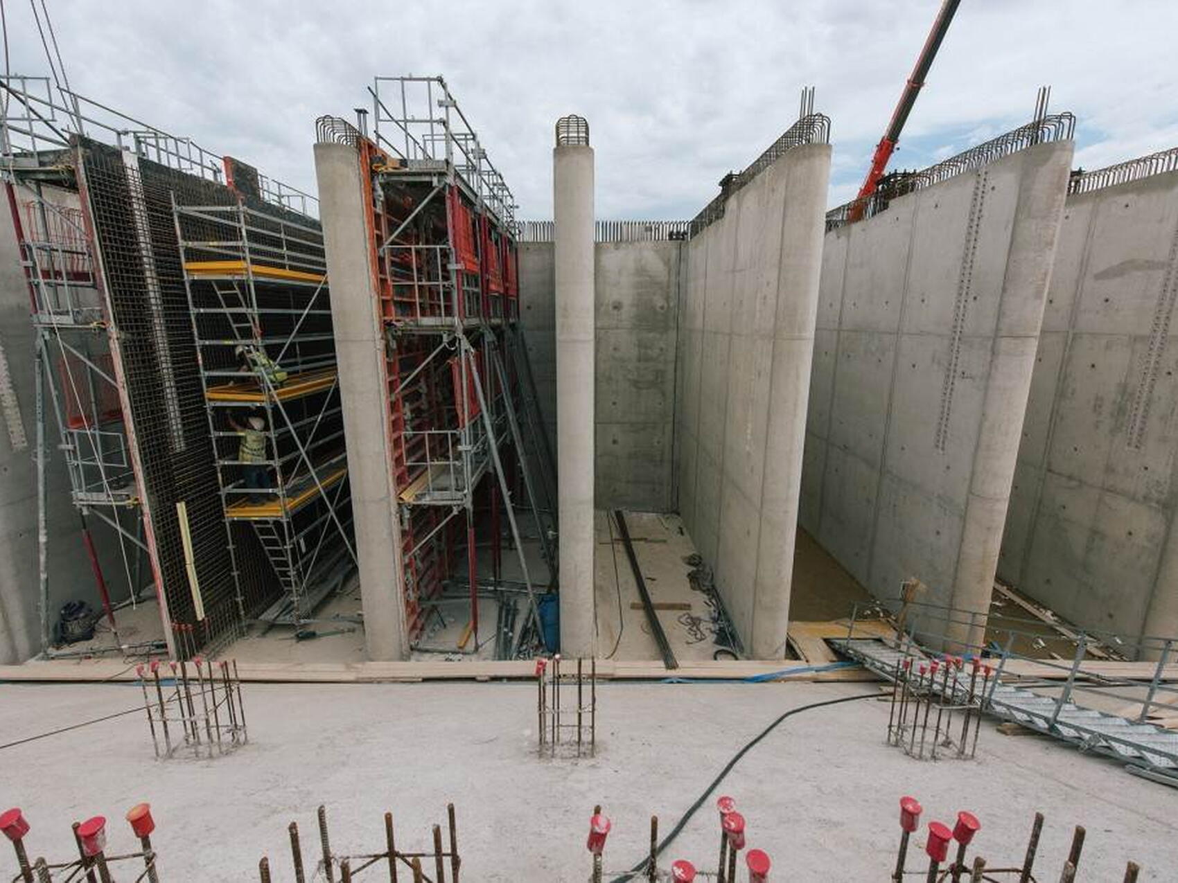
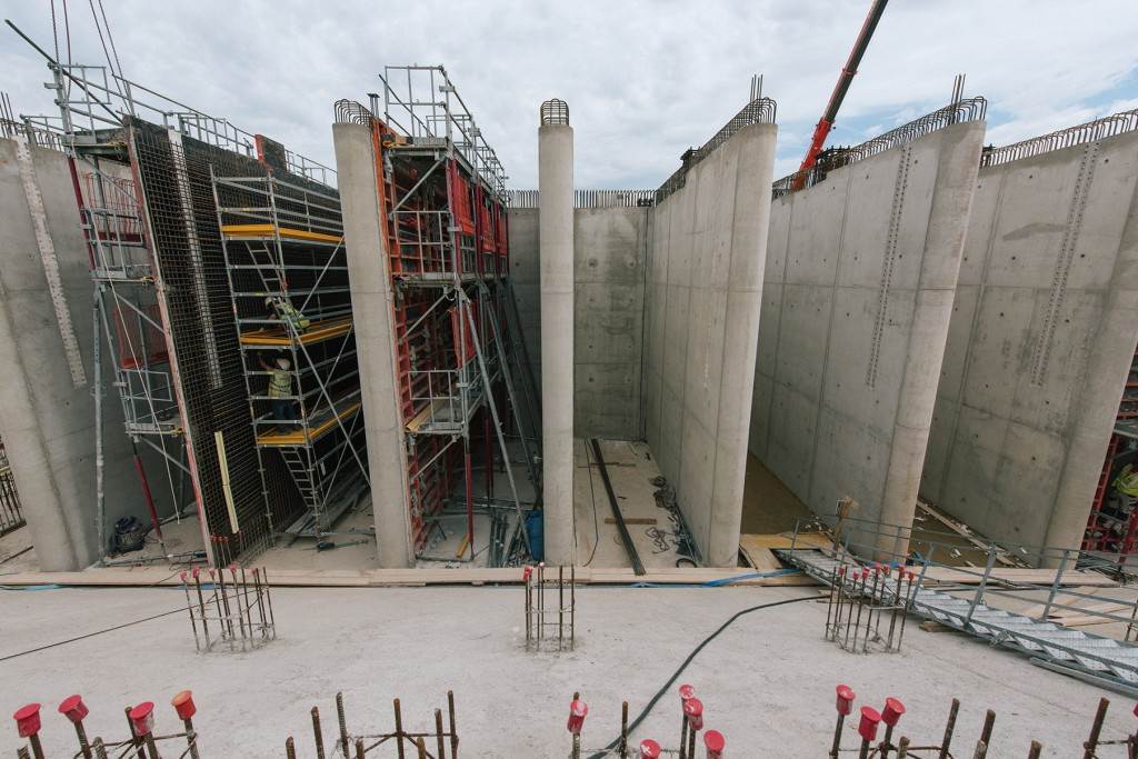
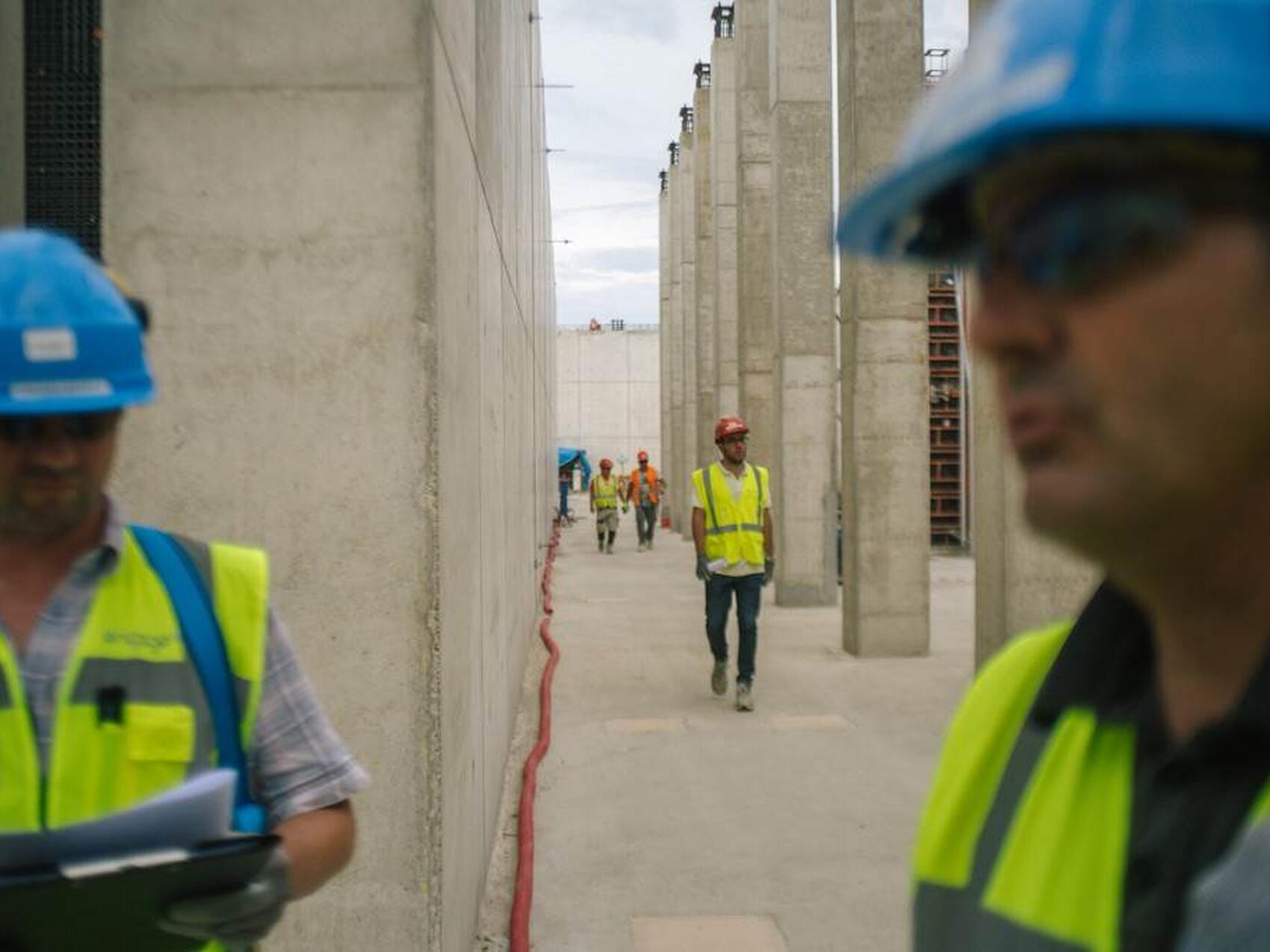
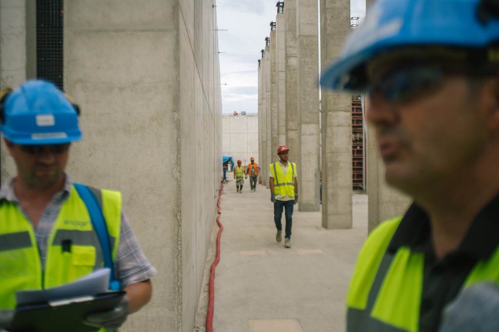
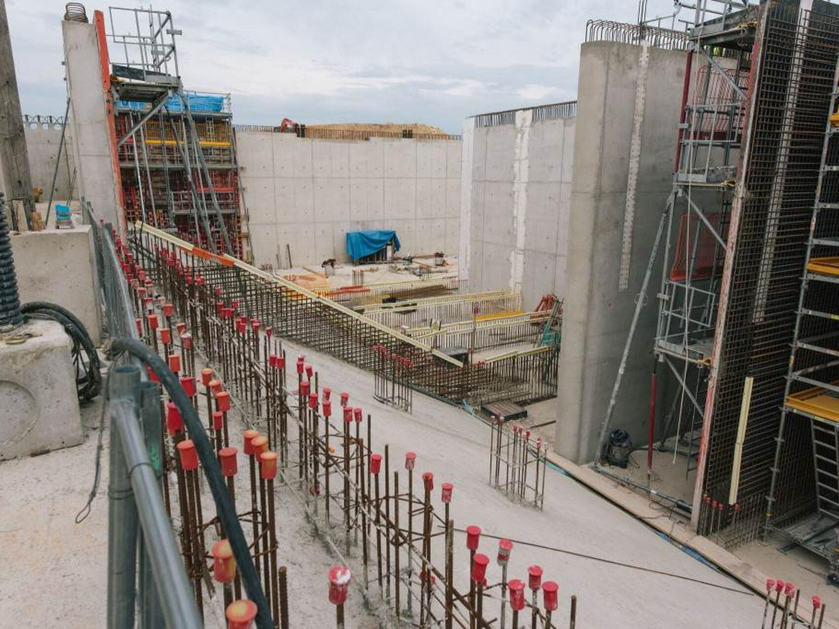
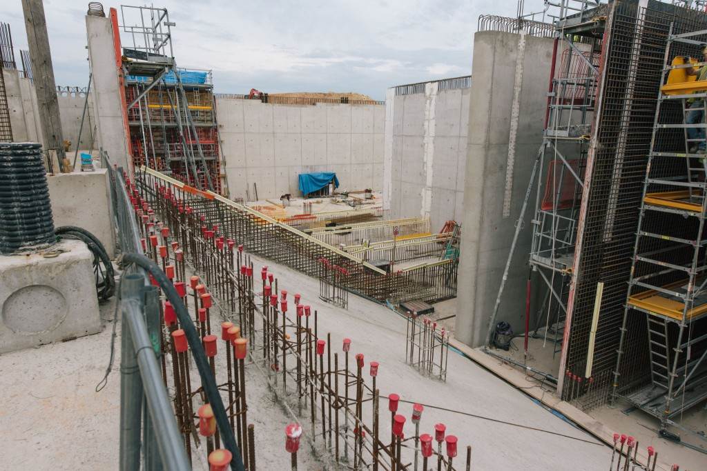
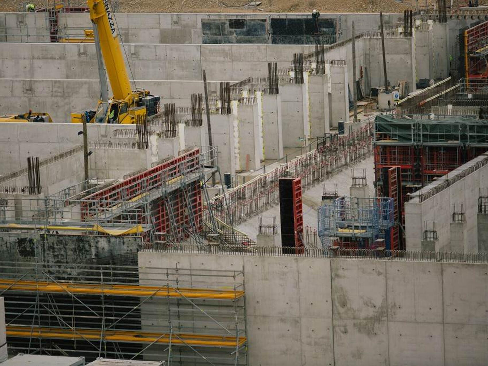
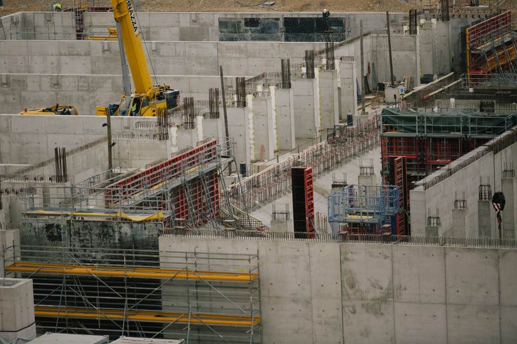
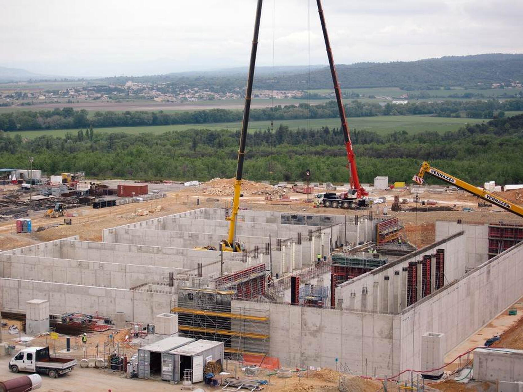
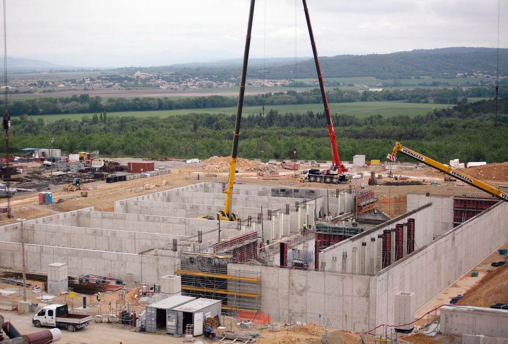
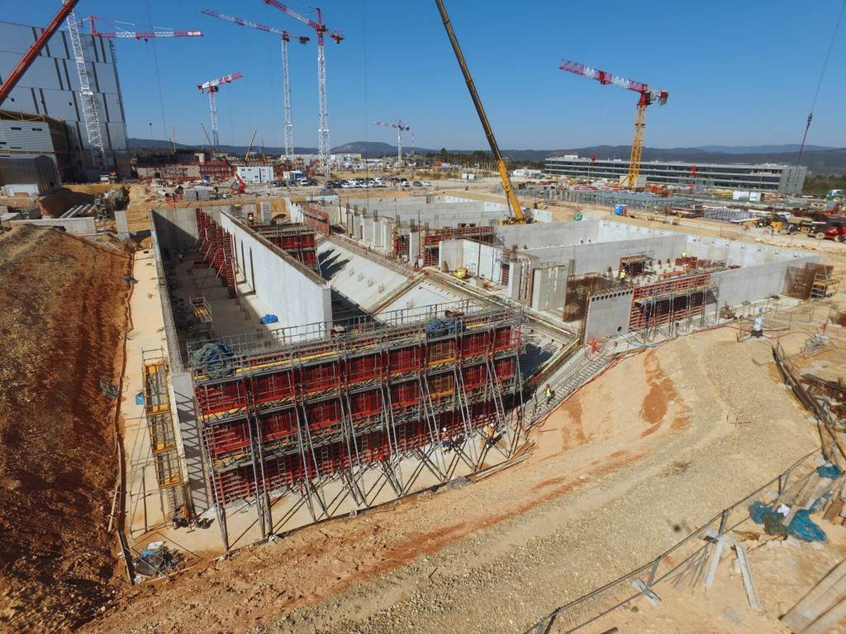
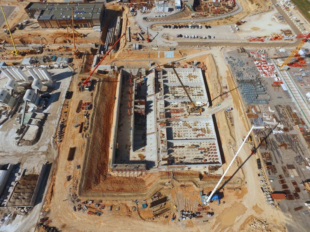
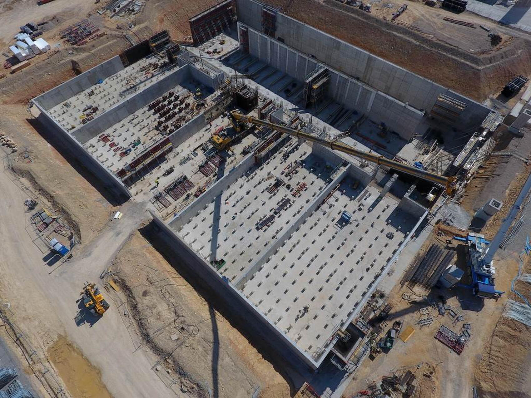
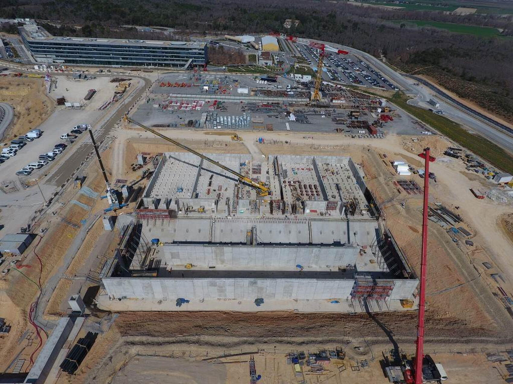
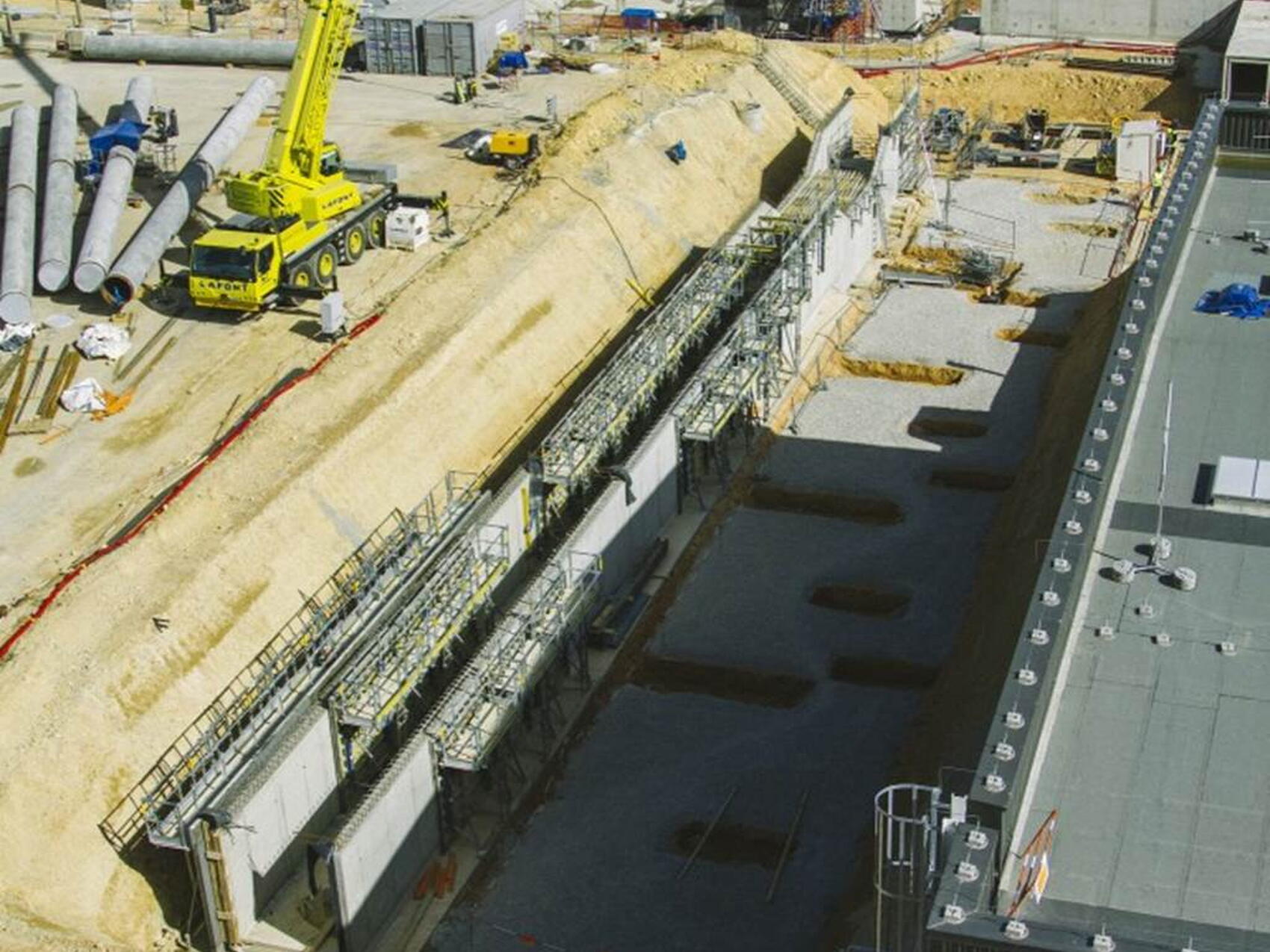
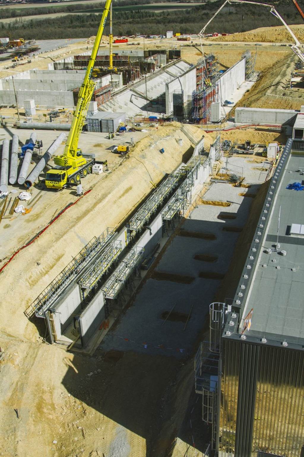
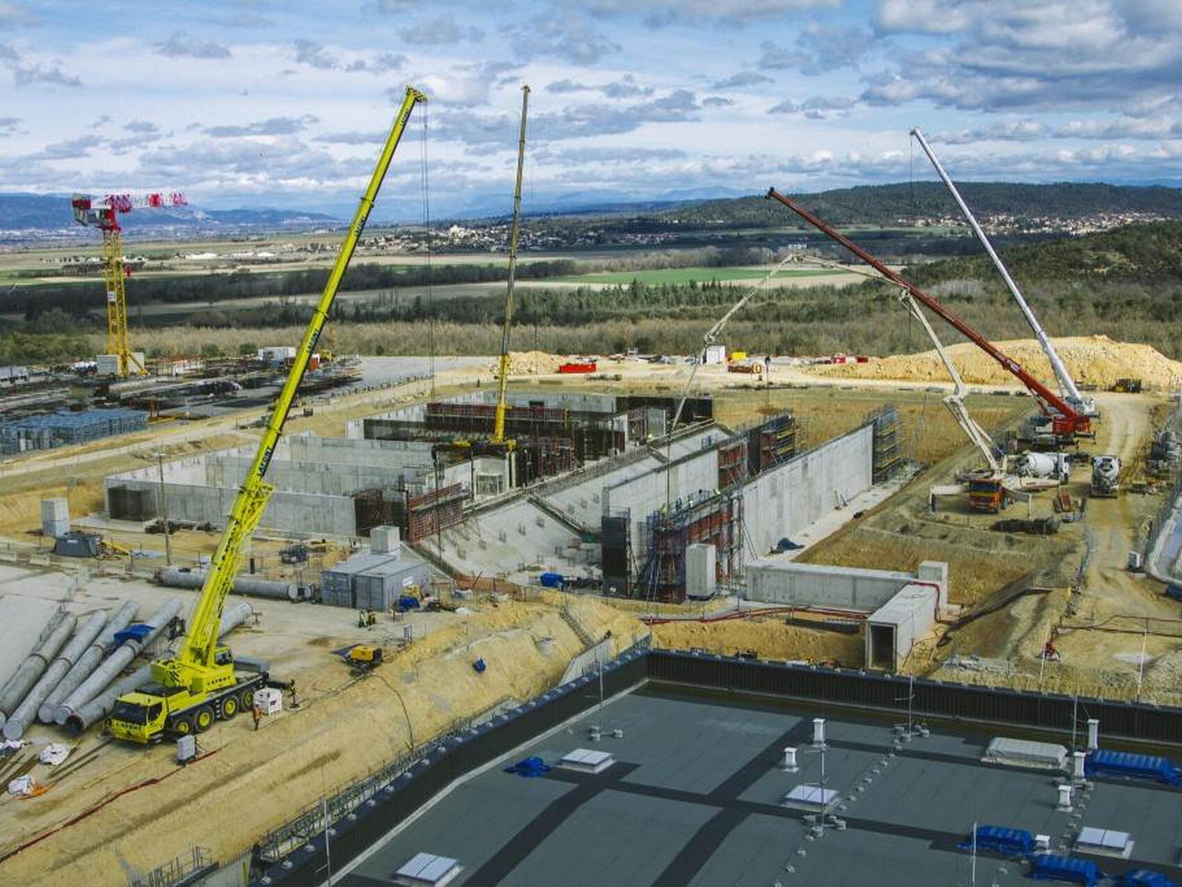
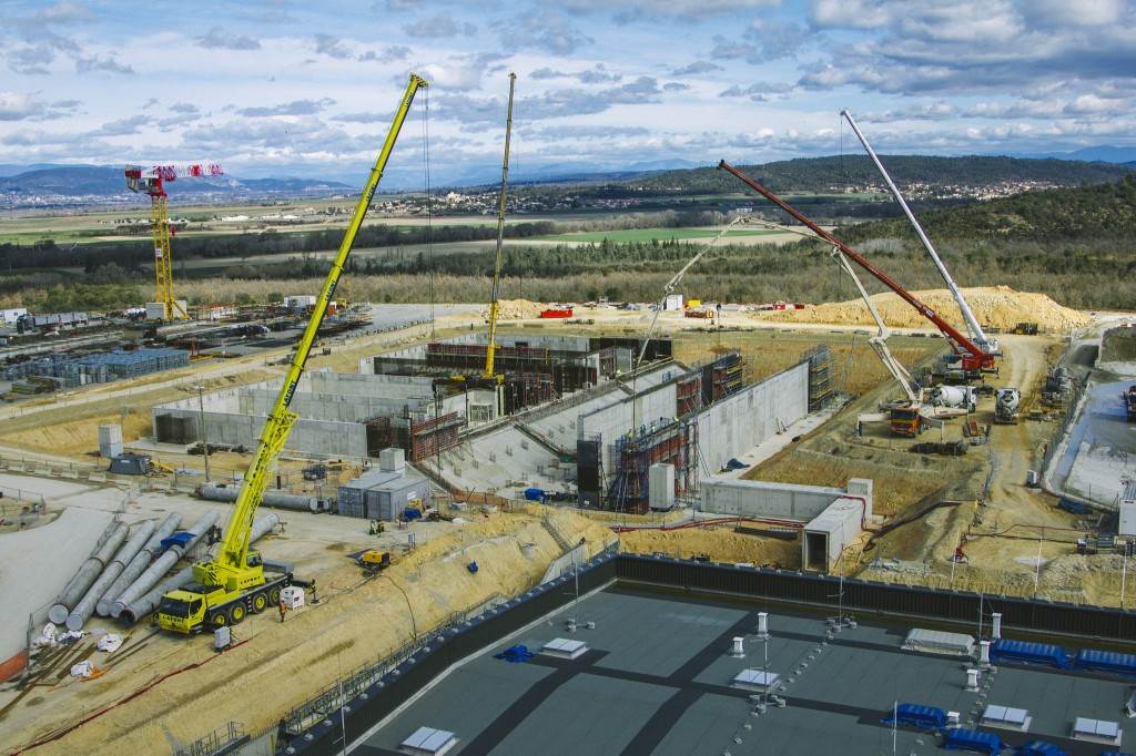
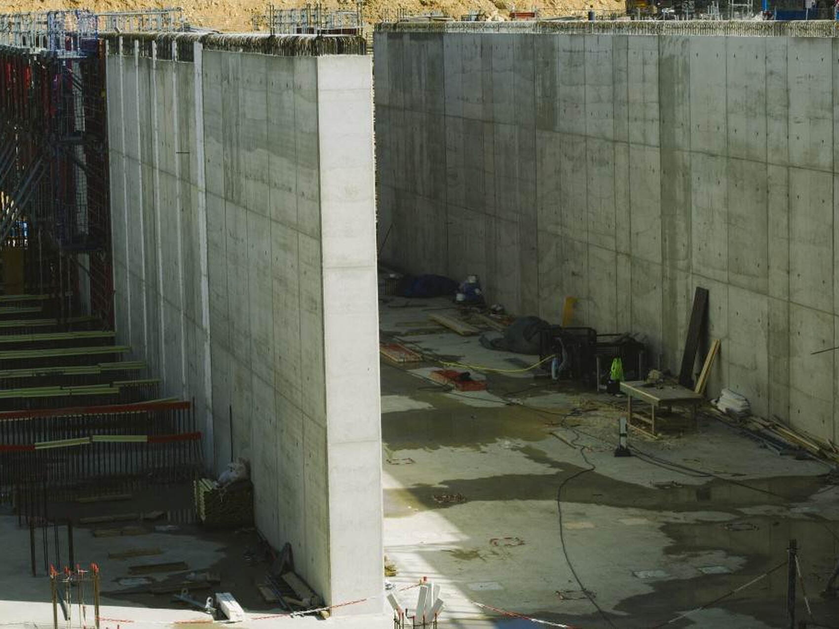
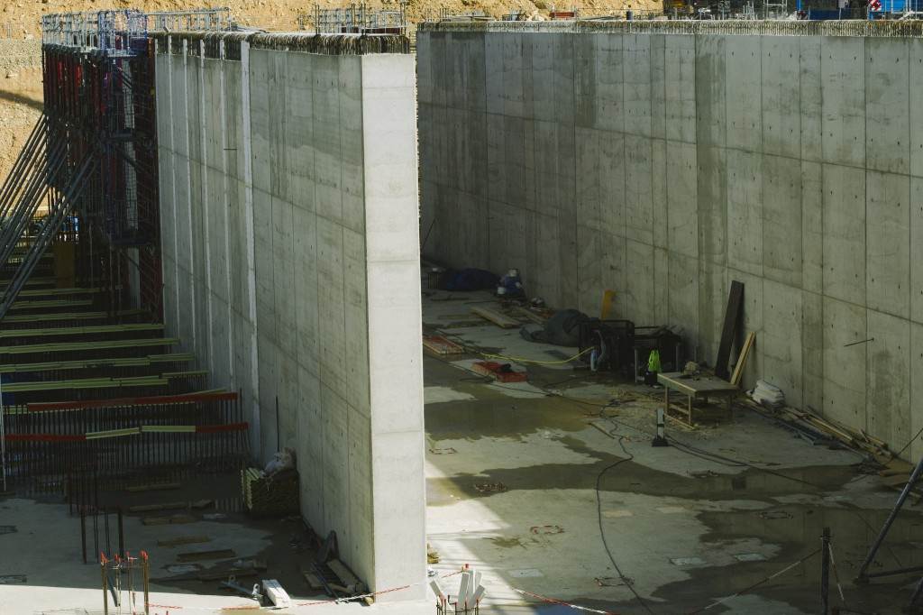
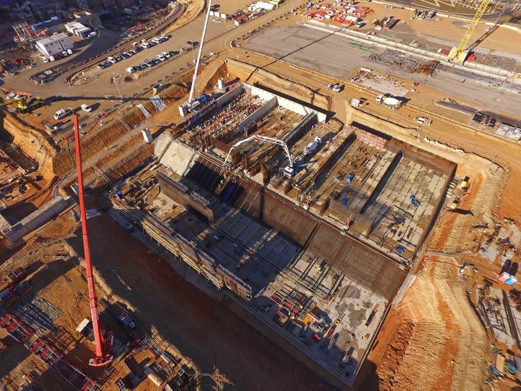
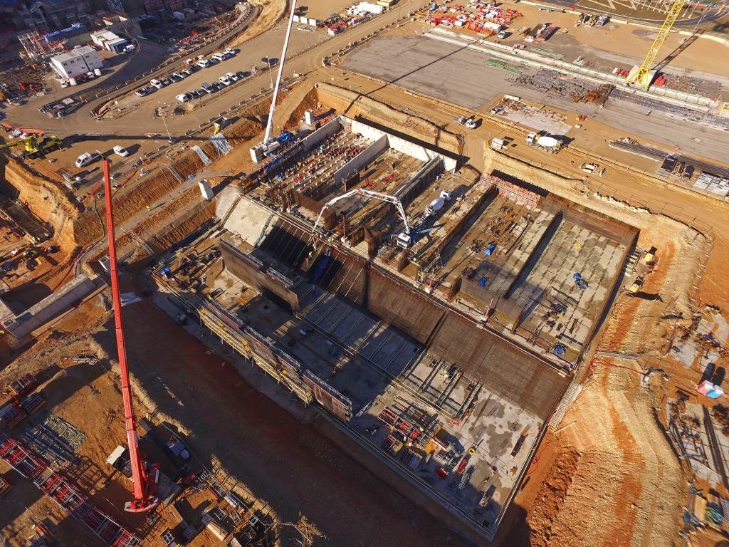
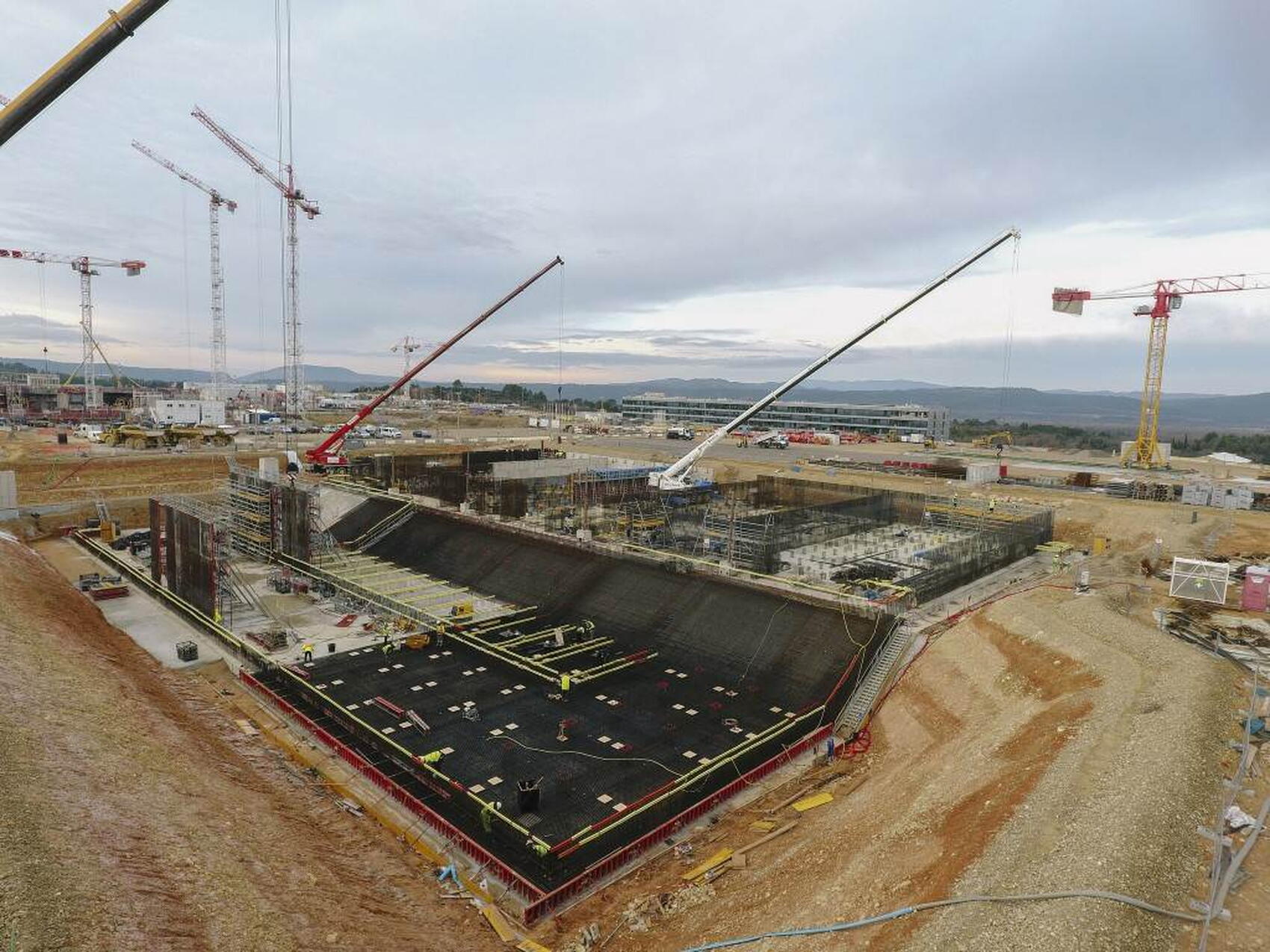
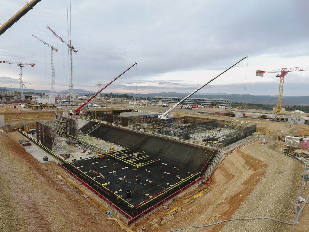
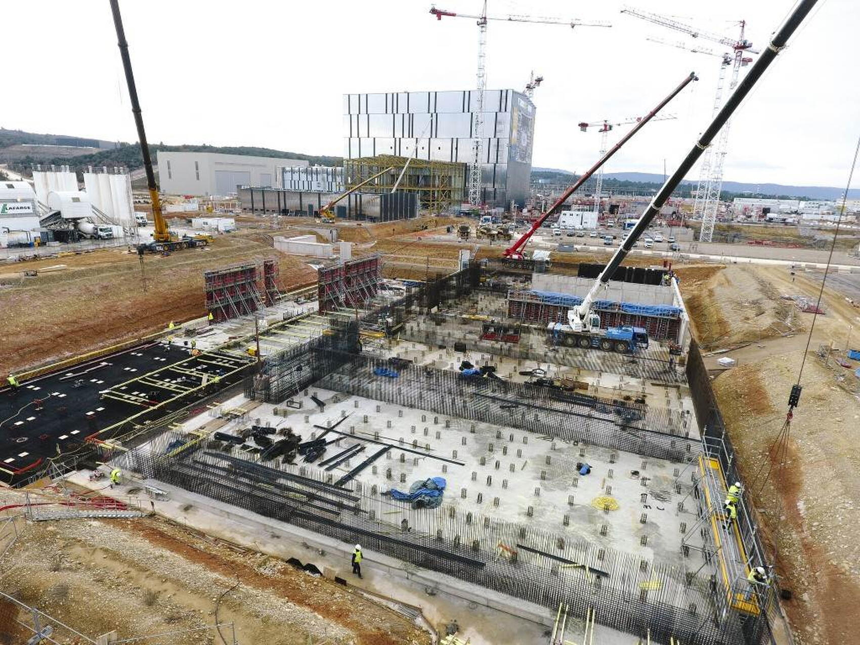
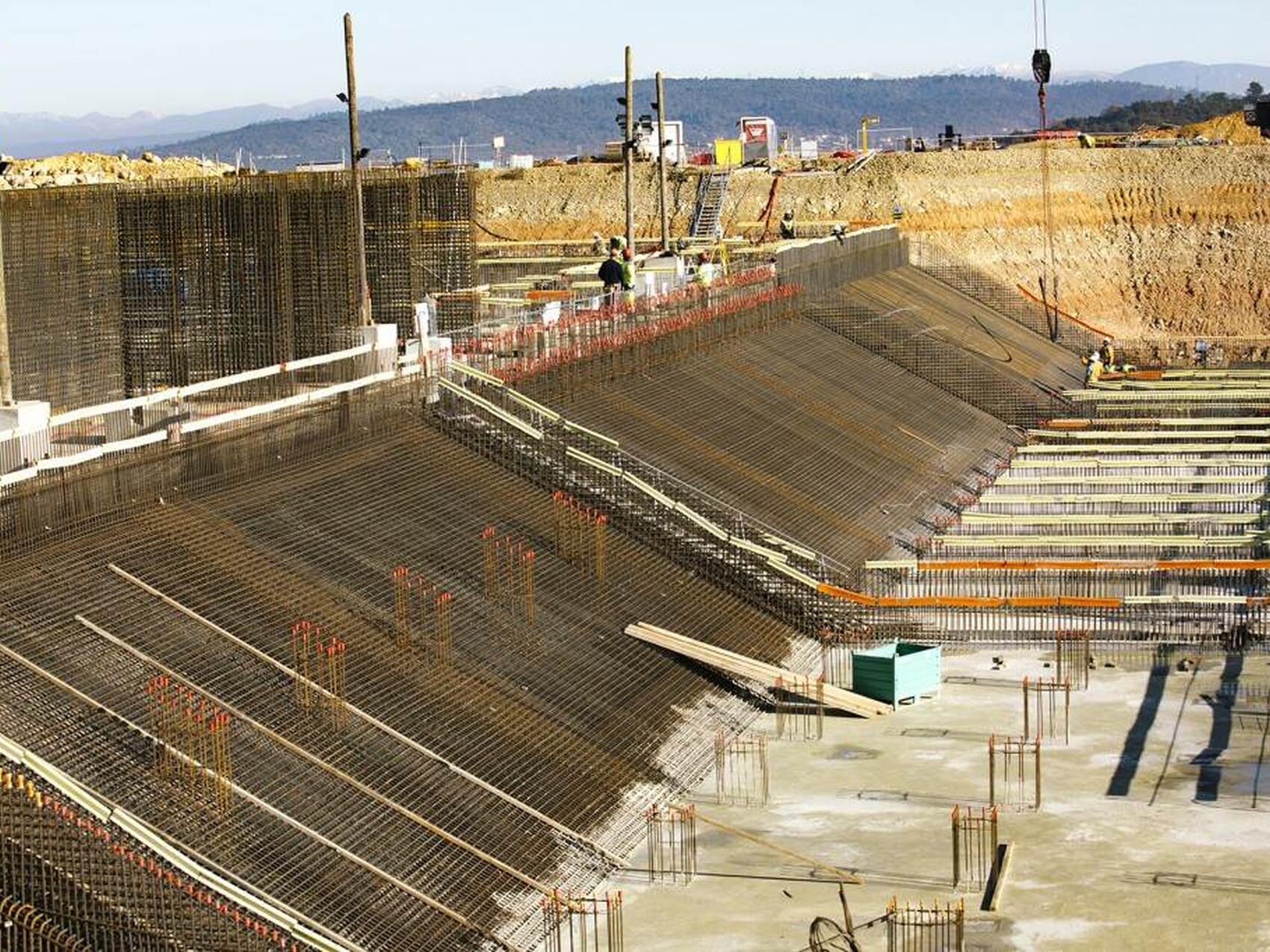
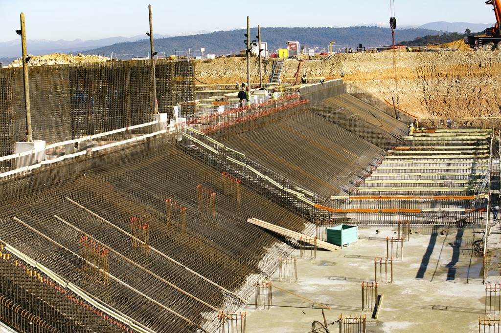
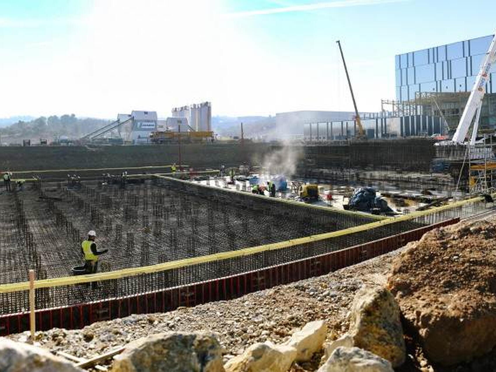
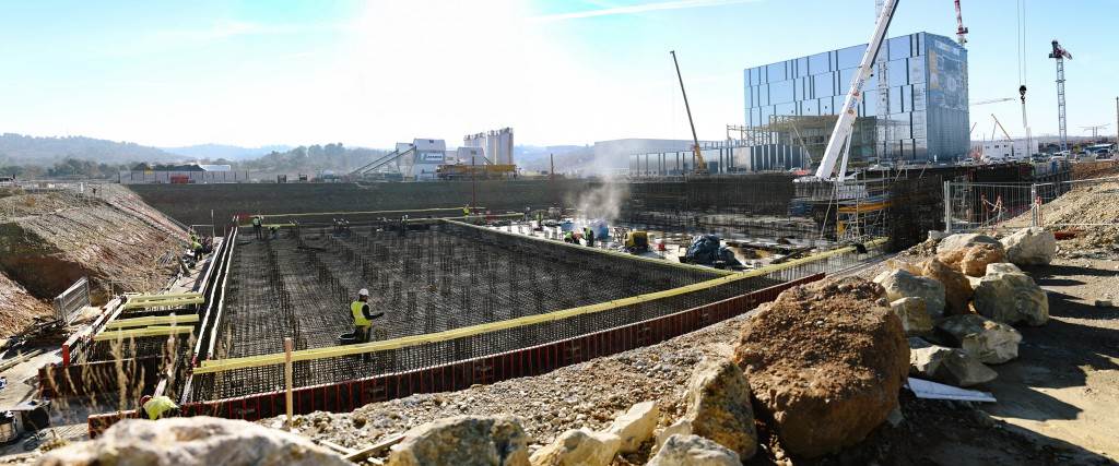
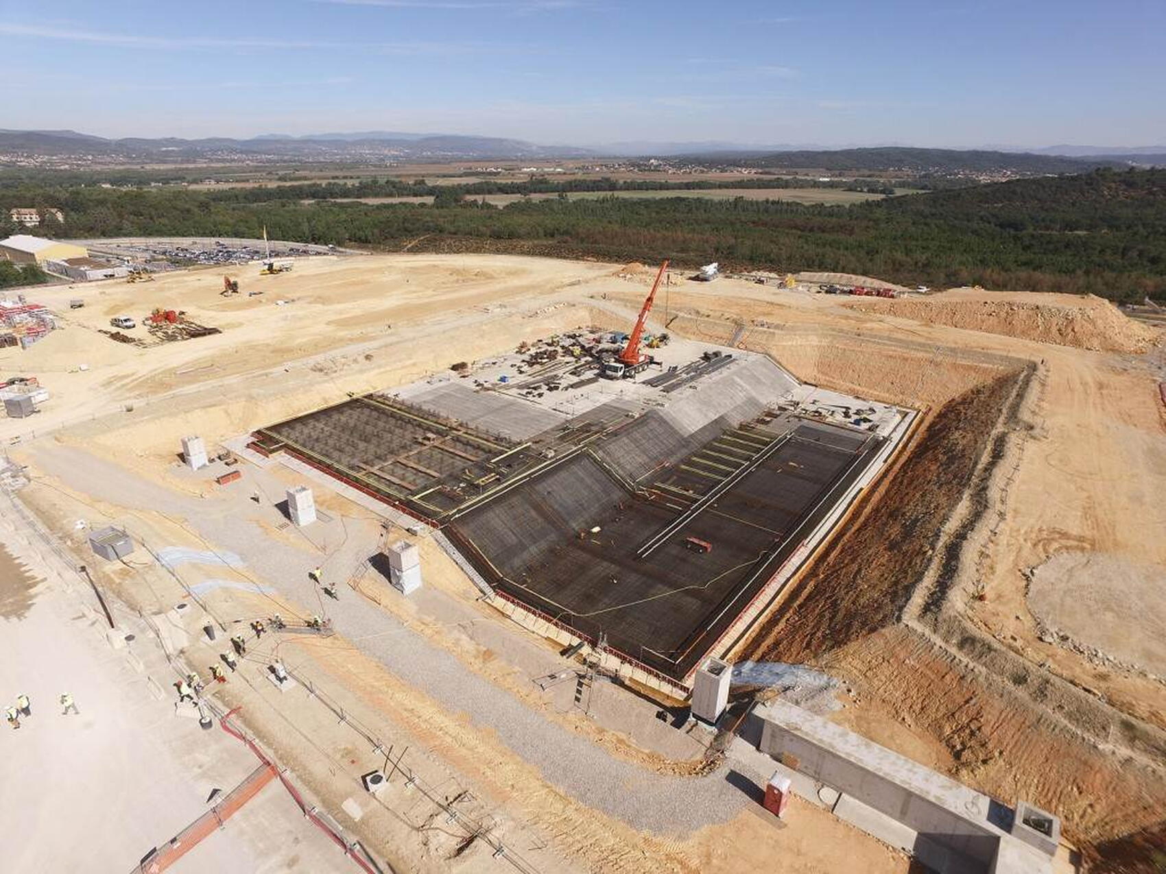
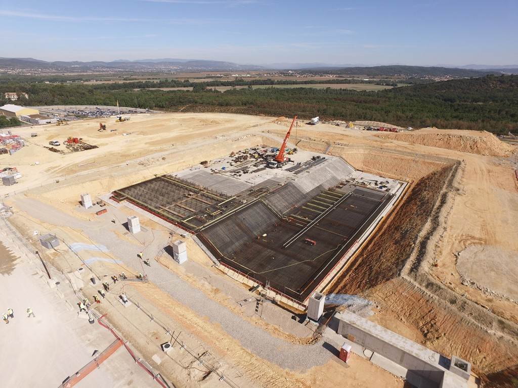
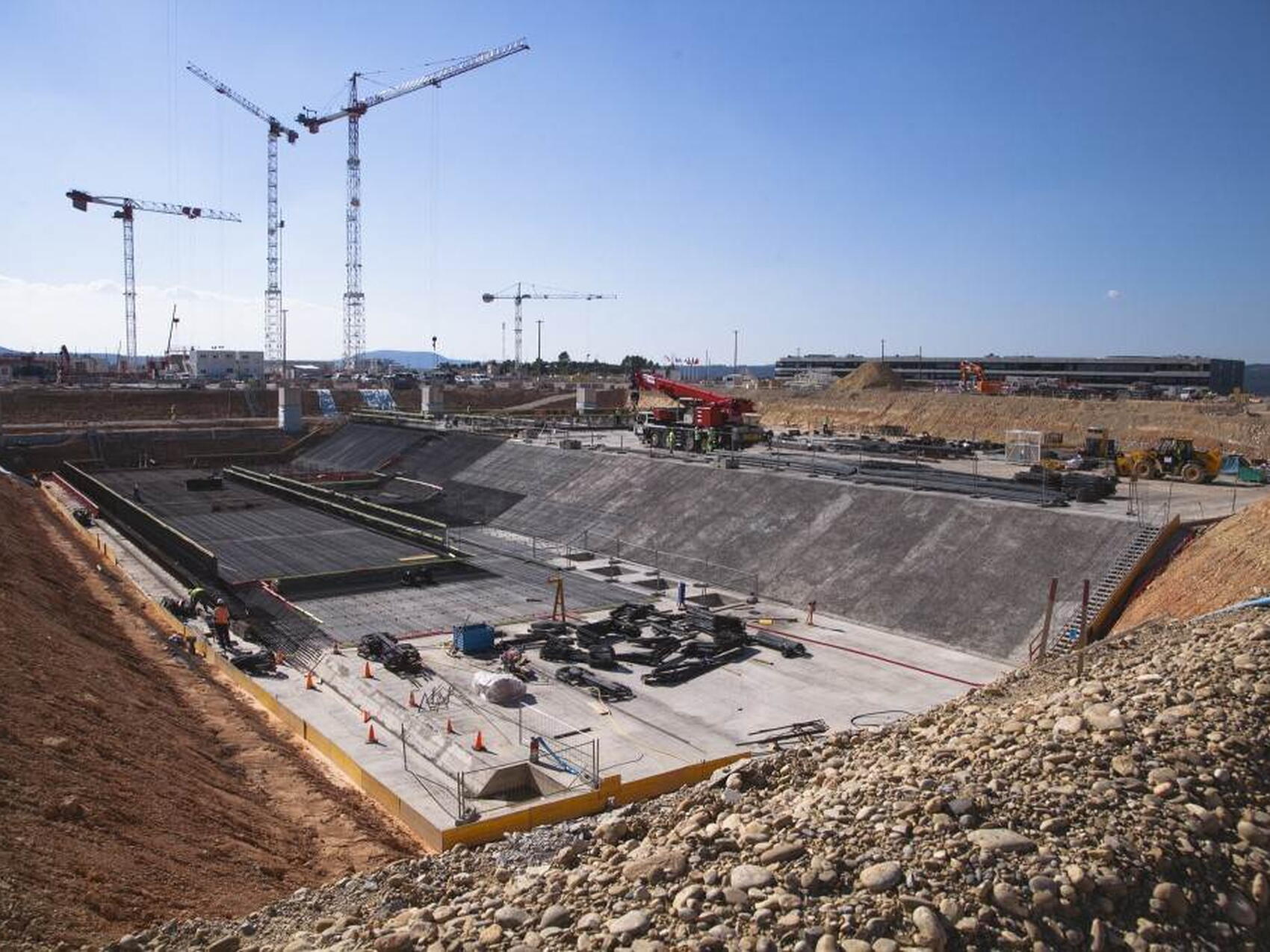
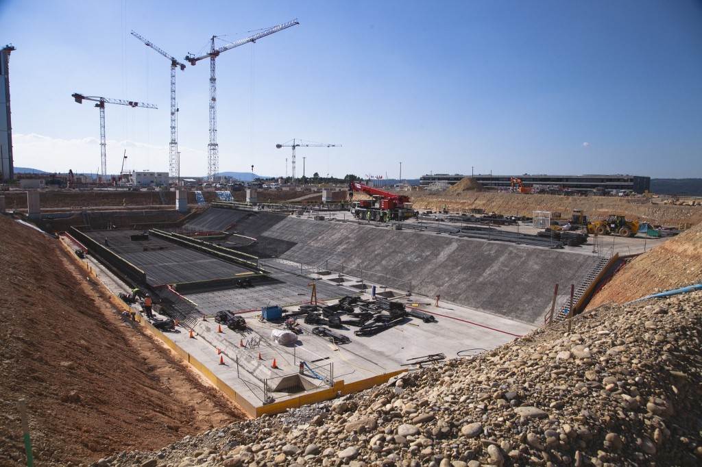
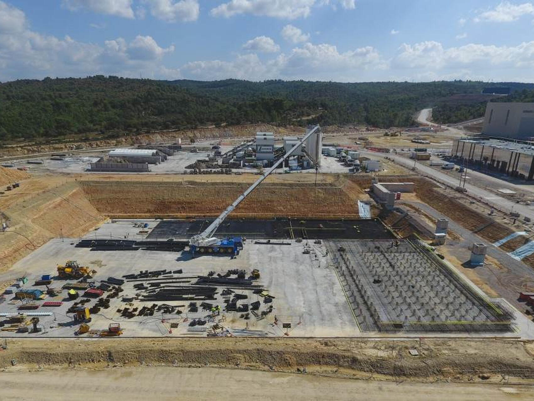
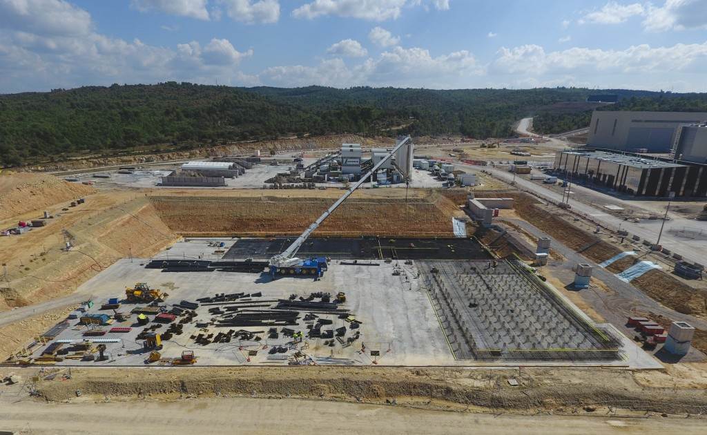
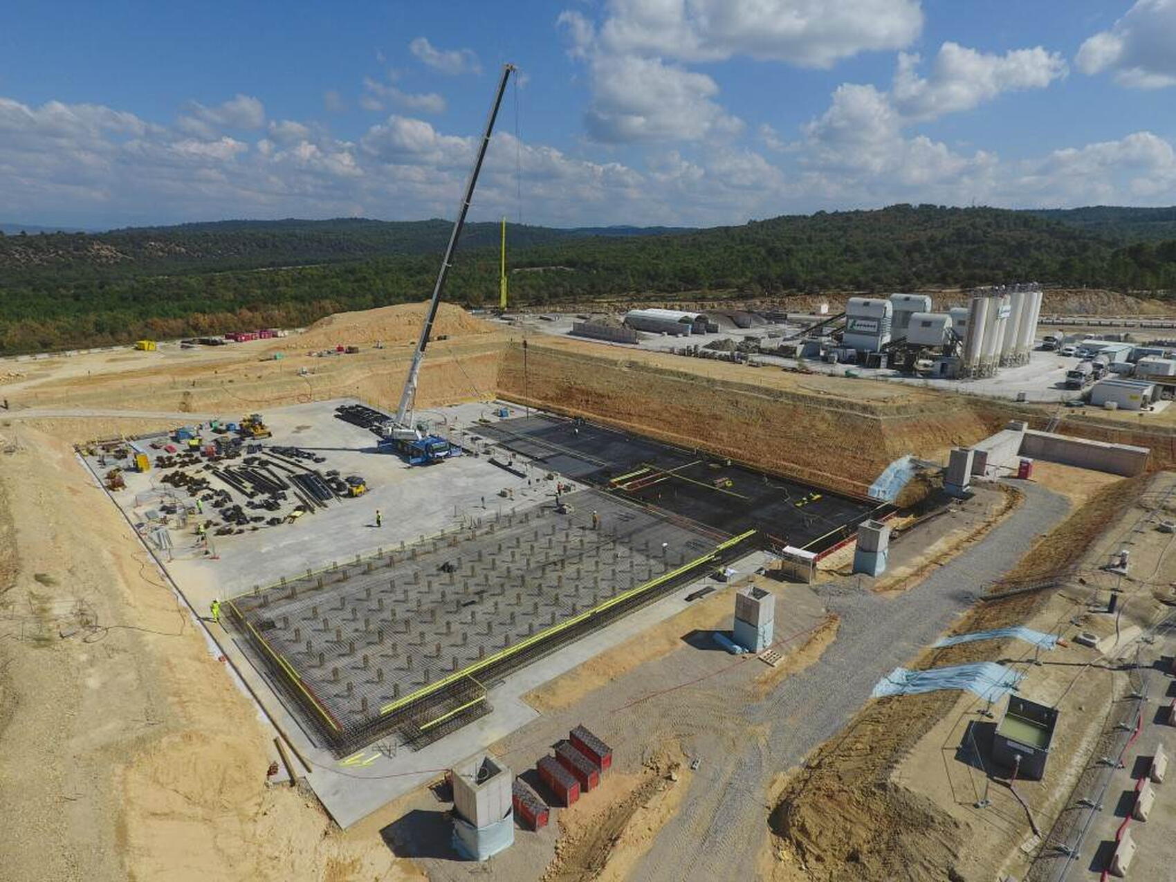
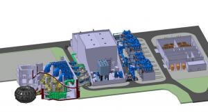
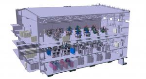
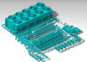
The heat rejection infrastructure is concentrated in a 6,000-square-metre area that comprises hot and cold cooling water basins, powerful pumps, heat exchangers, and an induced-draft cooling tower with ten individual cells.
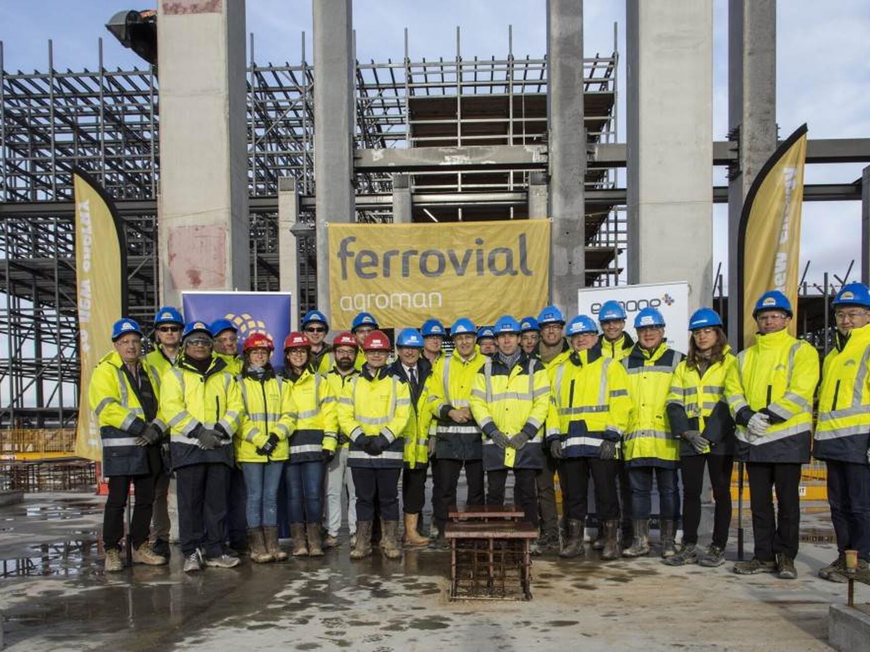
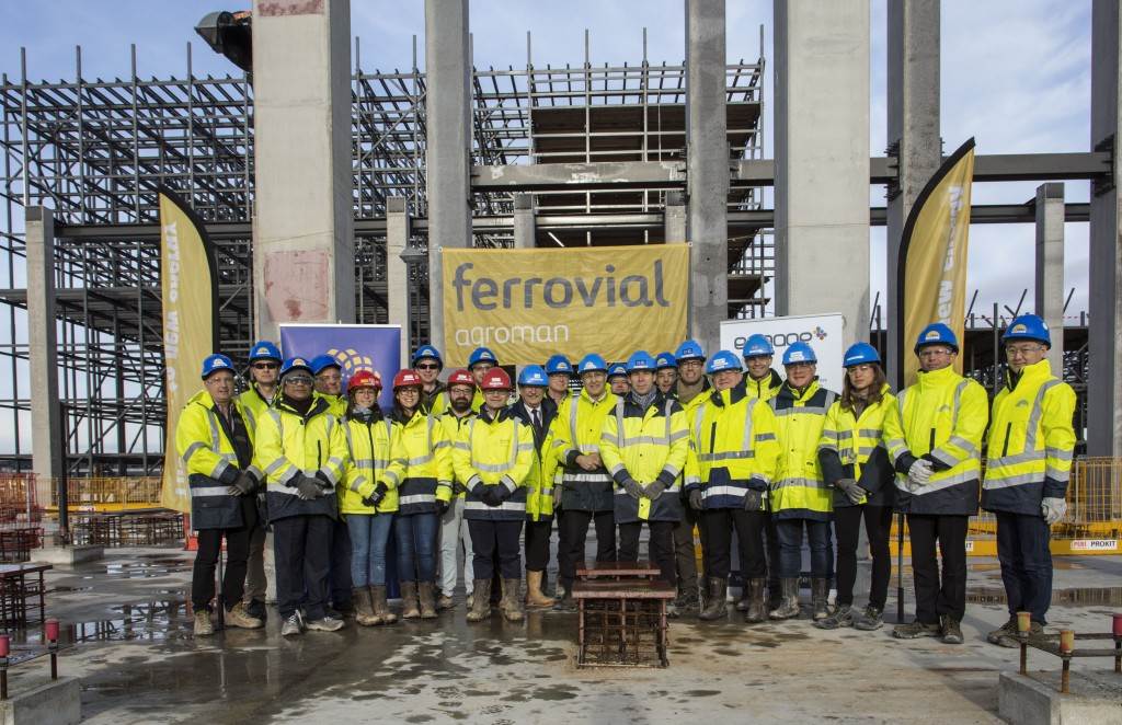
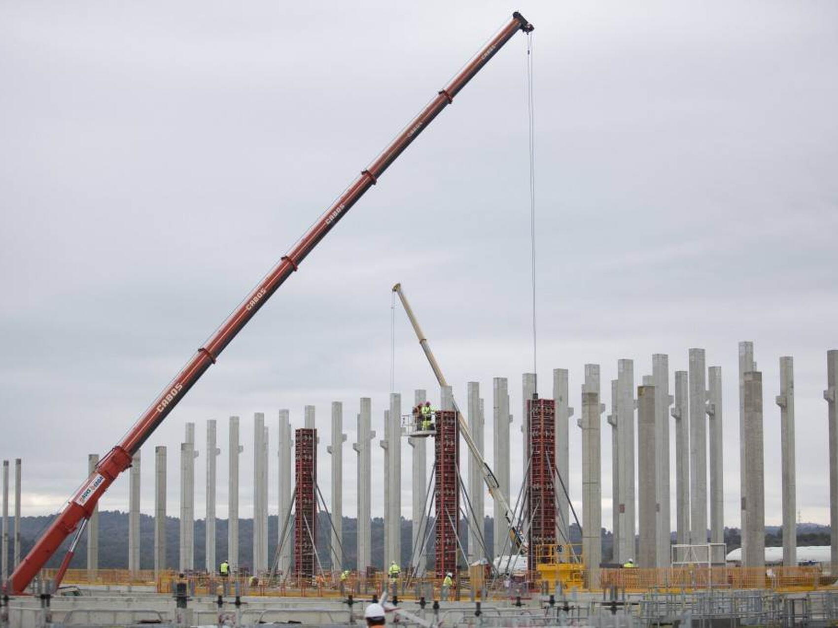
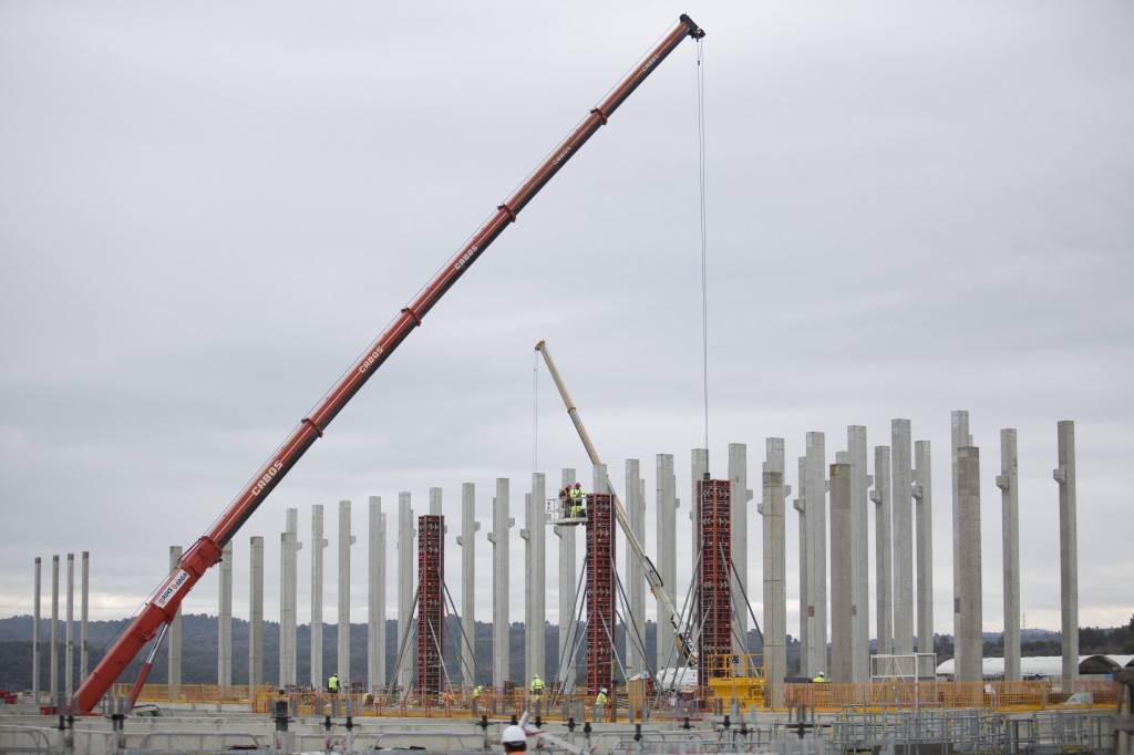
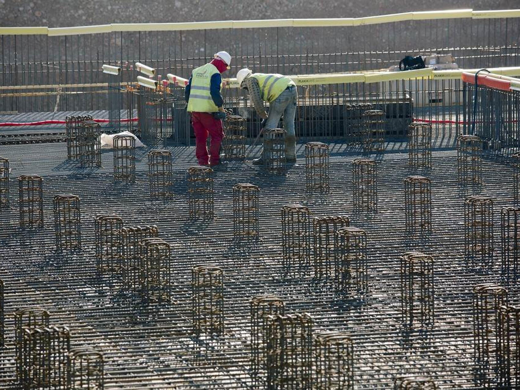
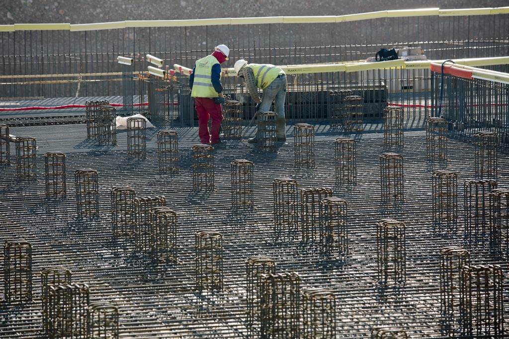
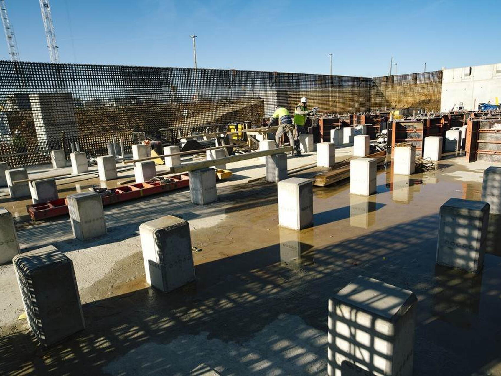
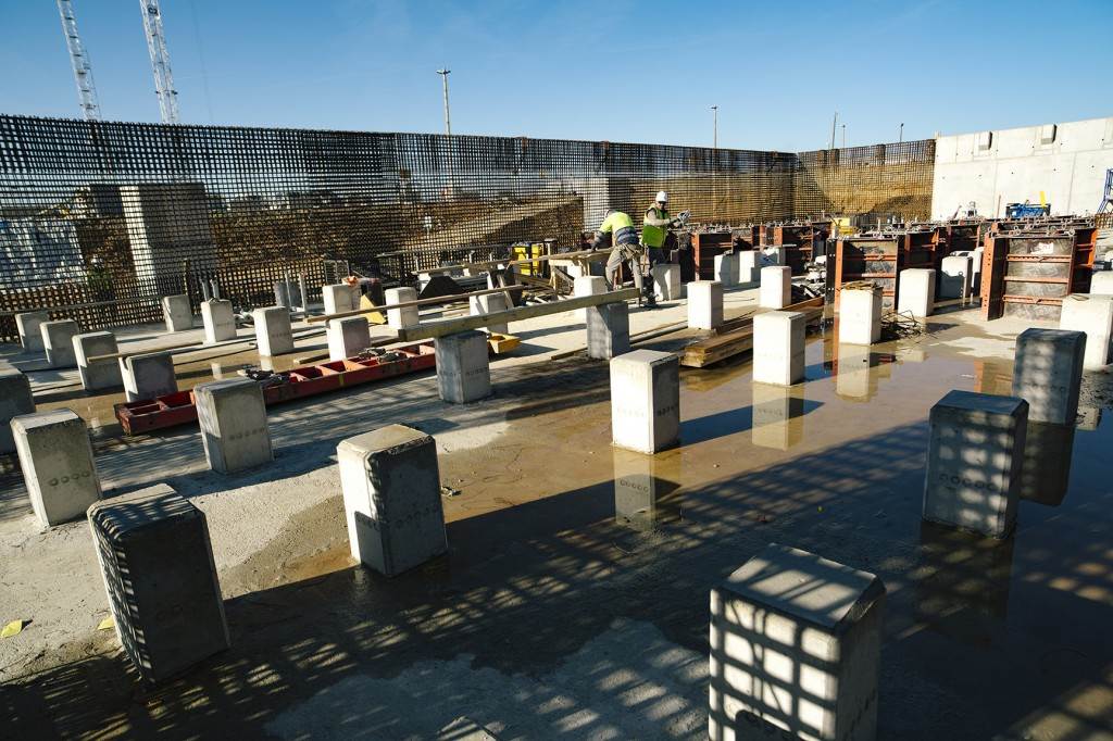
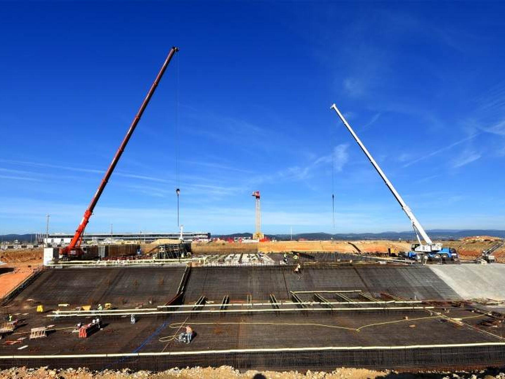
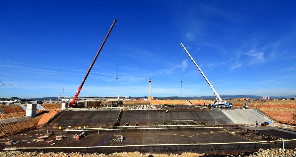
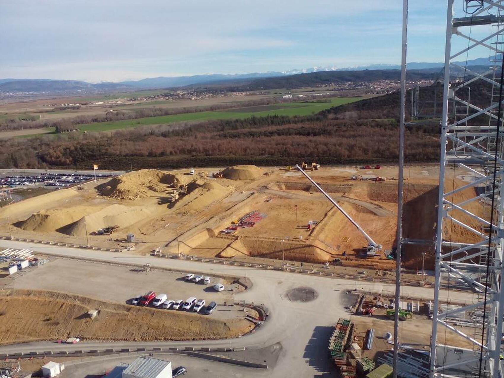
The design and fabrication of the heat rejection system are part of India's procurement contributions to the ITER Project. Europe excavated the site and created the concrete basins and structures; the ITER Organization installed all the equipment.
Heat rejection
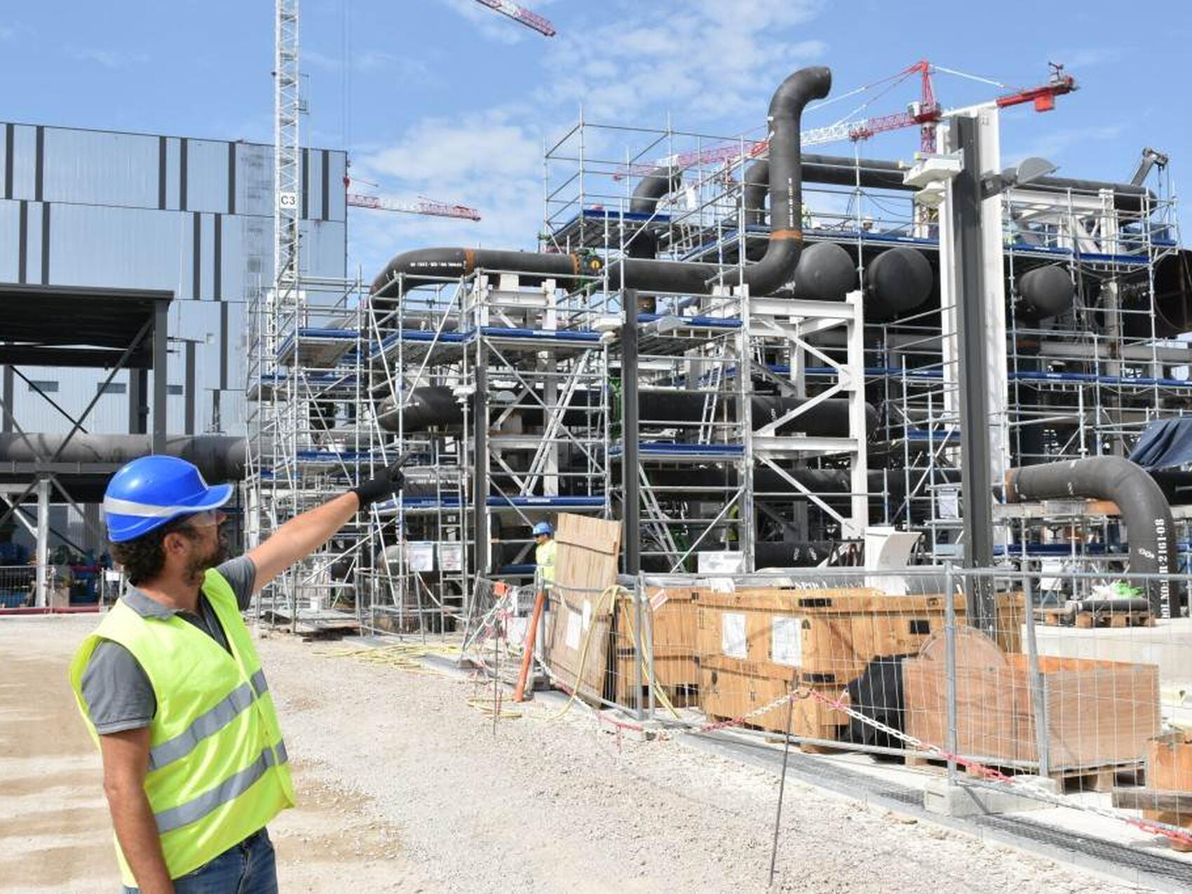
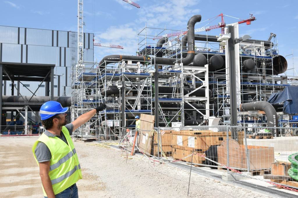
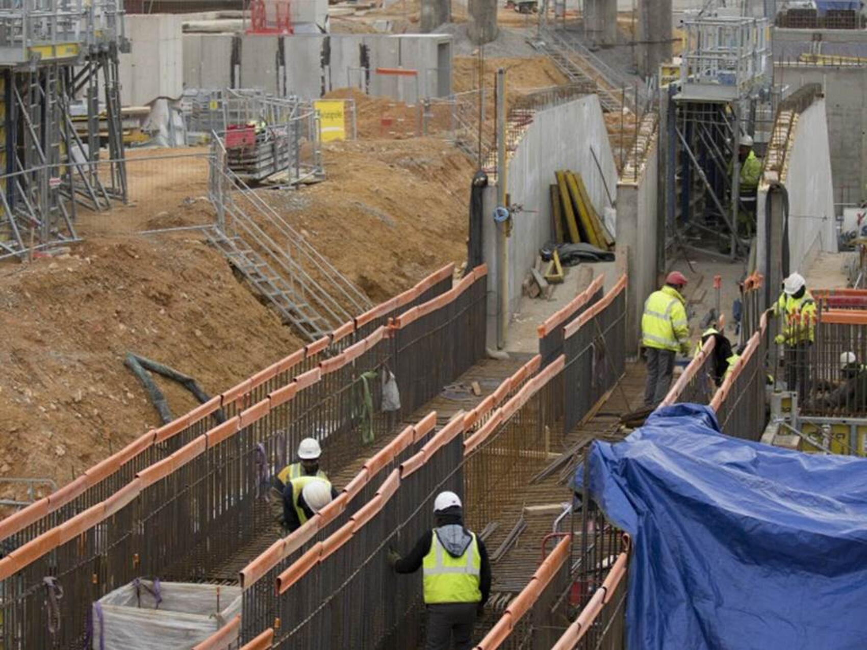
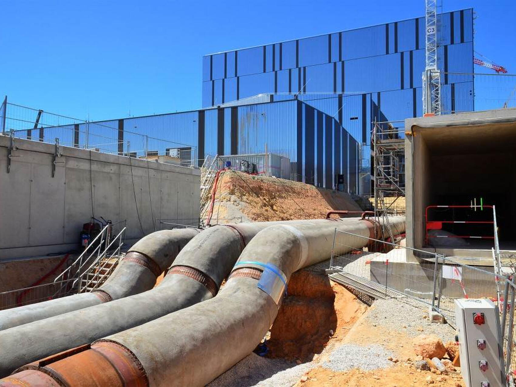
Heat generated during a plasma burn or dwell phase is collected by the tokamak's cooling water system (TCWS) and transferred through the component cooling water system loop 1 (CCWS-1) to the heat rejection system.
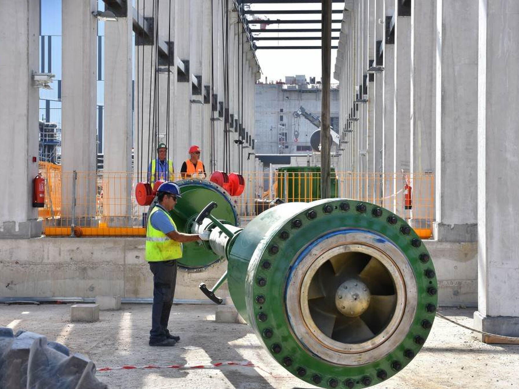
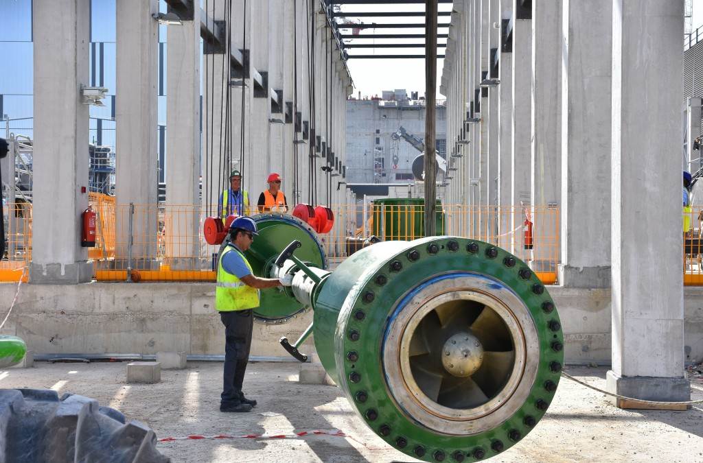
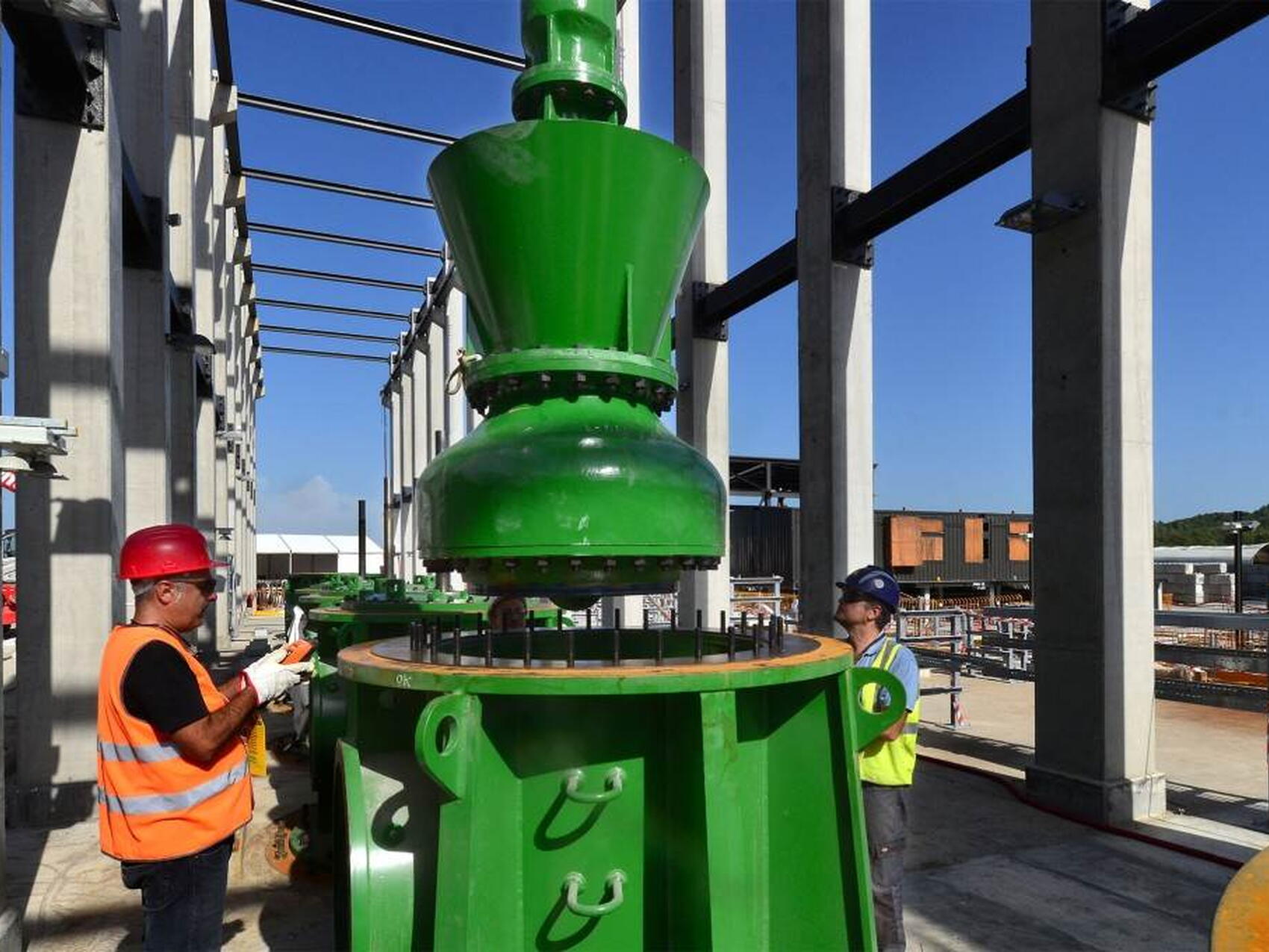
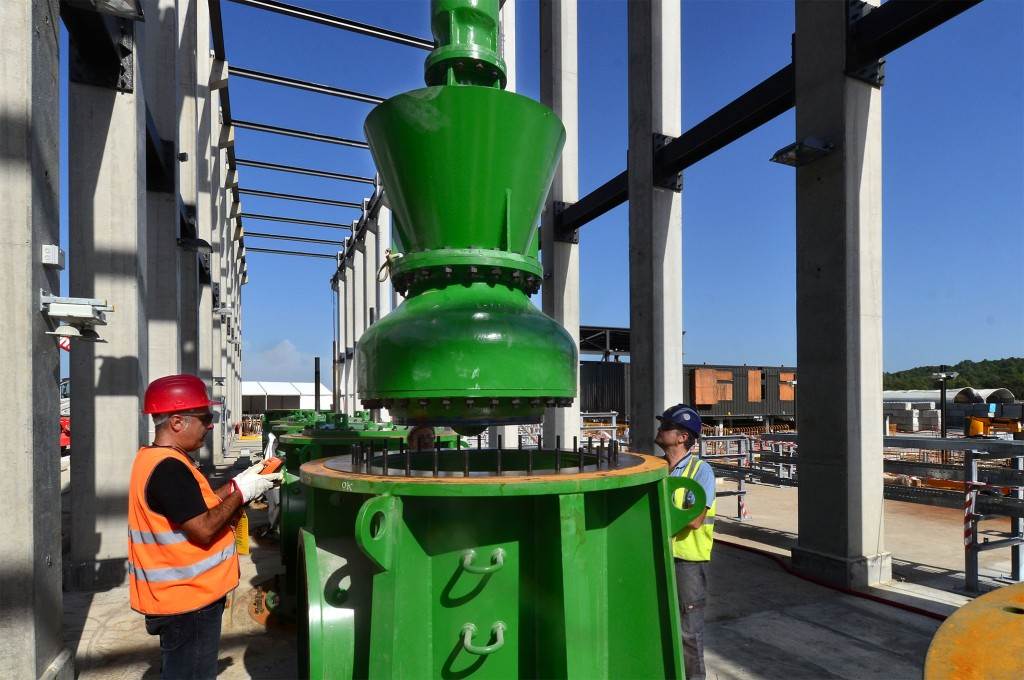
Water from CCWS-1—representing 85 percent of the total heat to be managed by the heat rejection system—is pumped through heat exchangers at platform level. The open loop heat rejection system draws water from the cold basin to cool these heat exchangers and discharges it to the hot basin. During the burn phase water can enter the hot basin at up to 65 °C, while during the dwell phase the temperature remains under 35 °C.
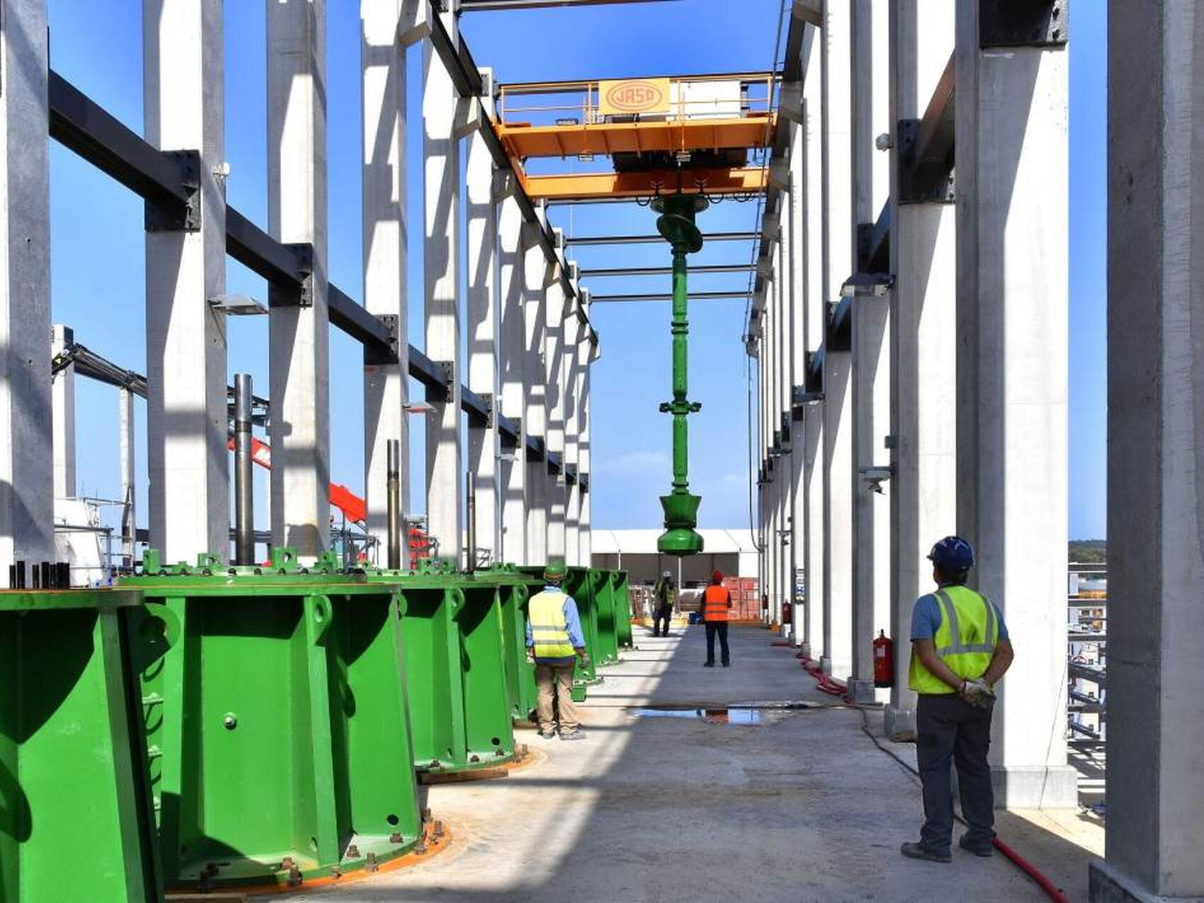
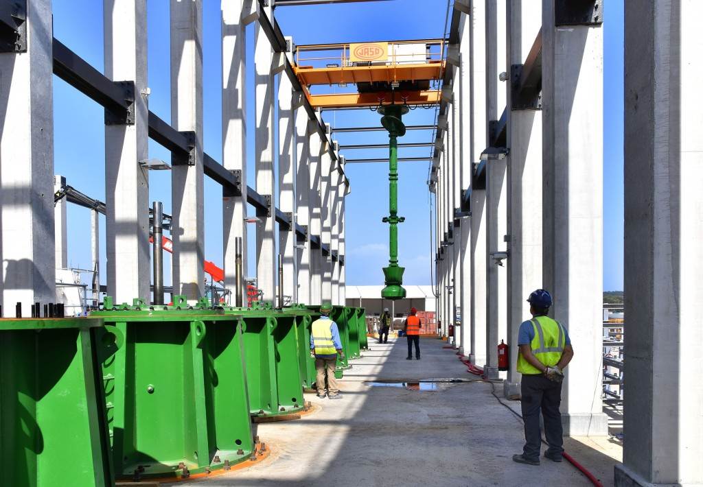
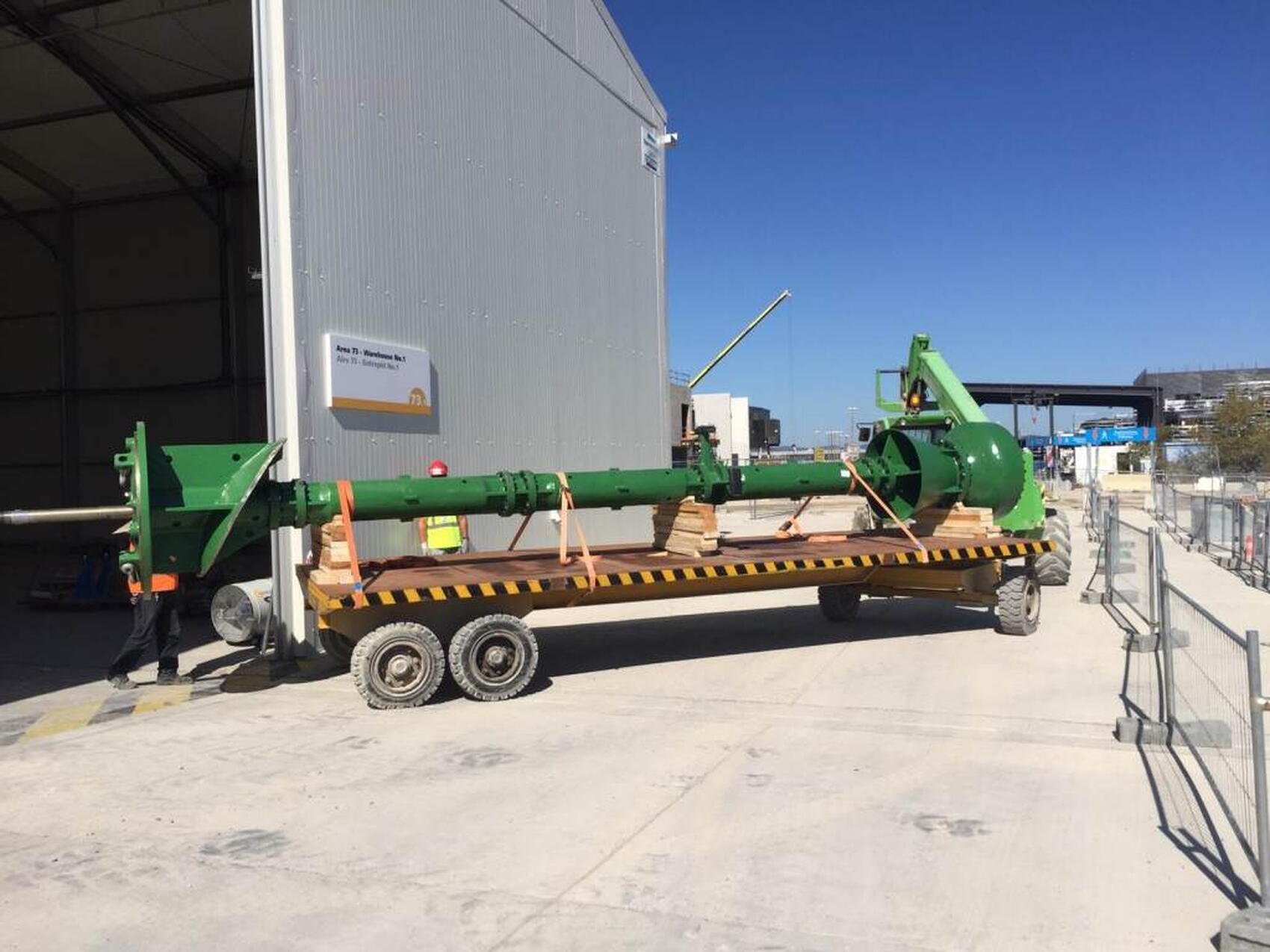
The cooling tower is designed for a specific water inlet temperature and works most efficiently if that temperature remains relatively constant. In order to maintain hot basin temperature as close as possible to the cooling tower design temperature, the vertical pumps that cool the CCWS-1 heat exchangers are designed to substantially reduce flow during the dwell phase when there is little heat coming from the Tokamak. Vertical pumps draw from the basin and discharge to the cooling tower at a steady rate, thus using the cooling tower efficiently throughout the entire 30-minute plasma cycle.
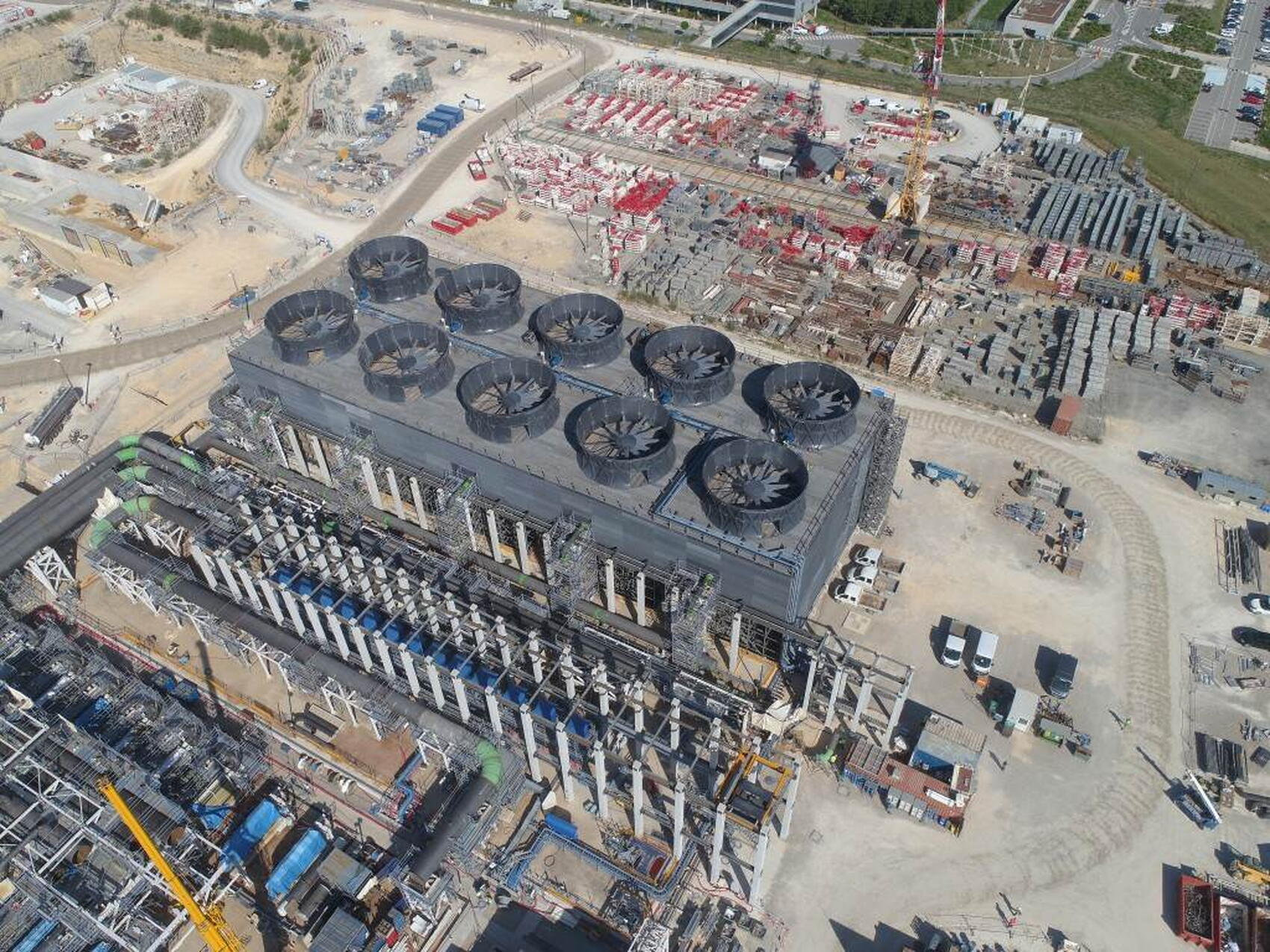
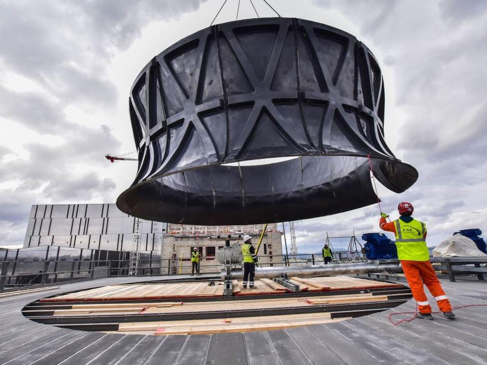
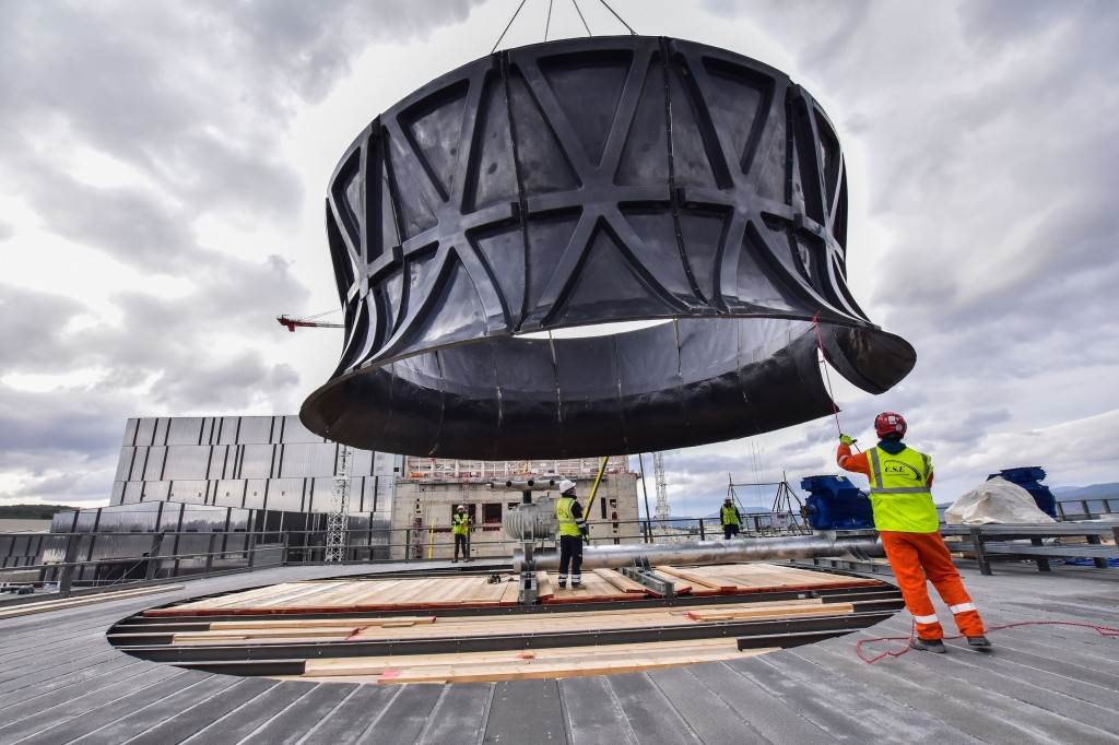
A second cooling loop (CCWS-2) collects the heat from auxiliary plant systems such as radio frequency heating, magnet power supply, and reactive power compensation. This cooling water, typically at a much lower temperature, is sent directly to the top of the 20-metre-tall cooling tower.
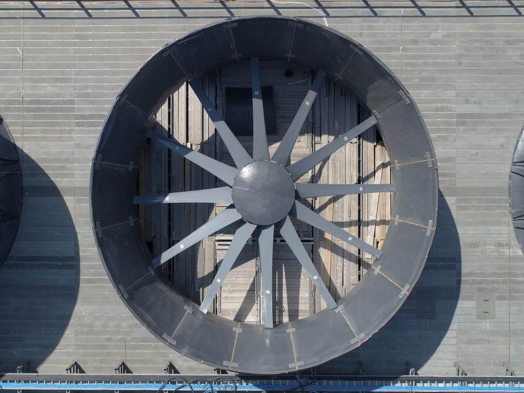
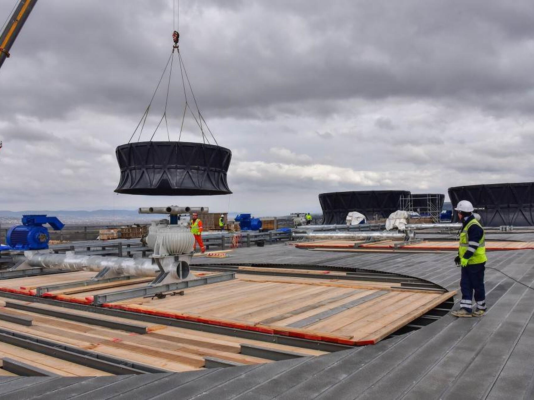
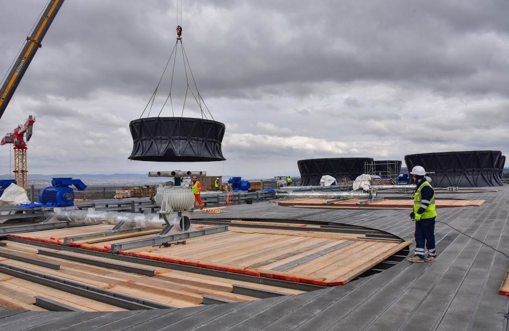
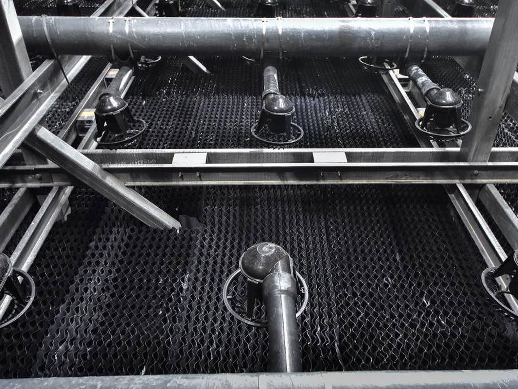
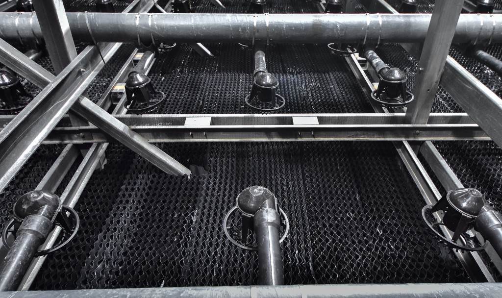
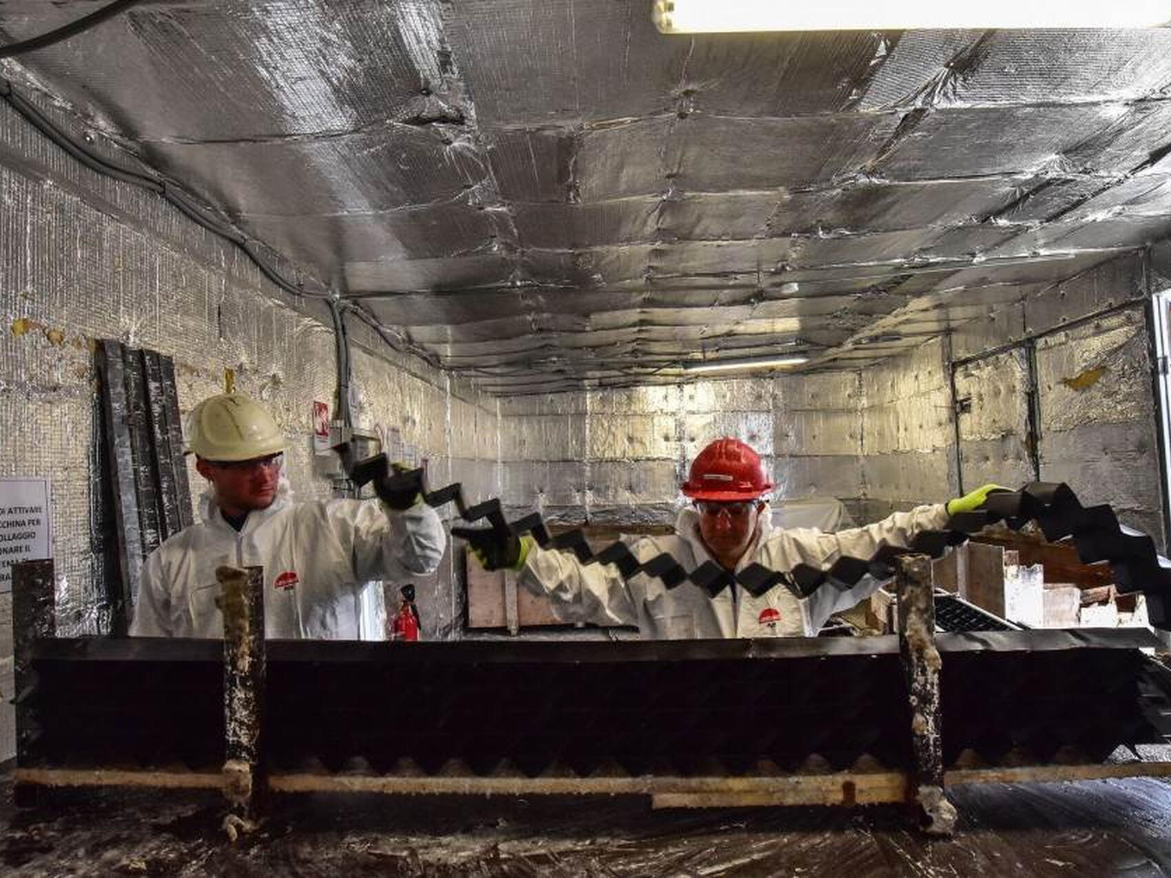
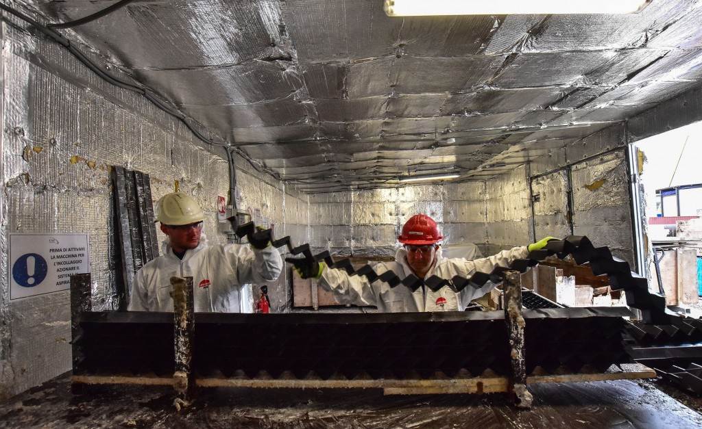
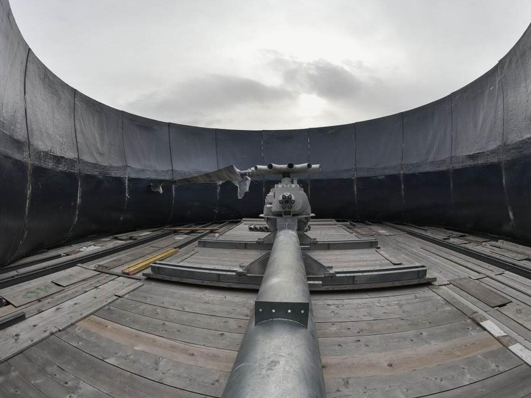
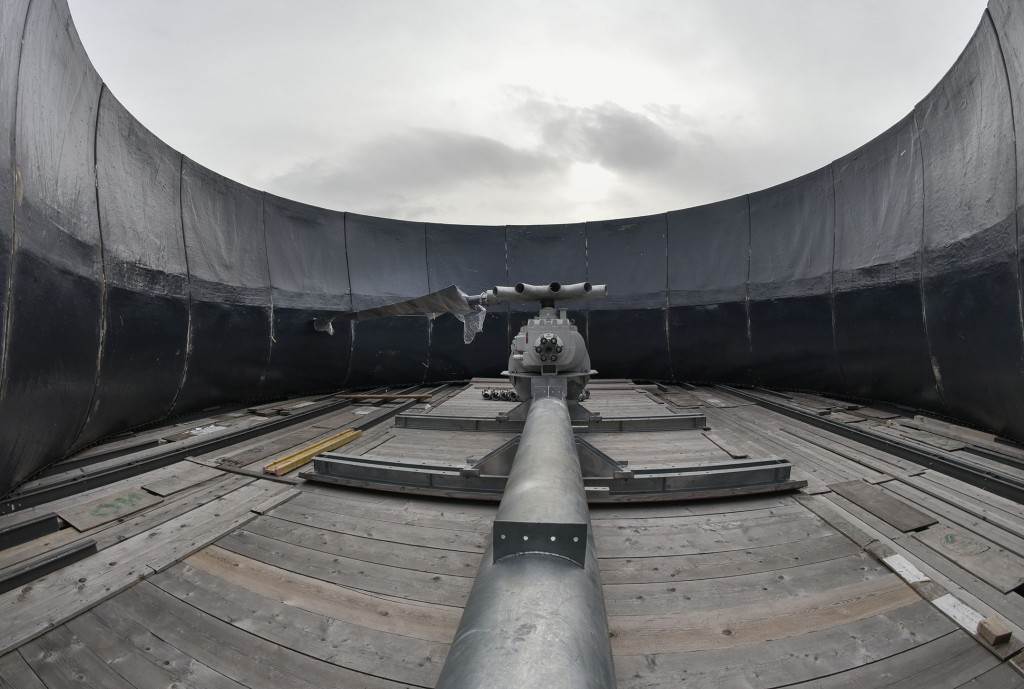
The ten cells of the cooling tower can be operated independently; ITER will start operation with just four. Each 16 x 16-metre cell is filled with hundreds of layers of corrugated plastic fill and equipped with a large fan that pulls air upward. As water falls through the fill, some of it evaporates due to the strong uptake of air, removing heat. The cooled water is collected in the cold basin located under the cells; from there, it is recirculated through the CCWS-1 and CCWS-2 heat exchangers. Control functions for the heat rejection system will be primarily managed from the ITER Control Building.
To maintain the quality of the water in the circuit, part of the water is continuously discharged to the Durance River via holding basins (blowdown flow), while fresh water is added from the Canal de Provence (make-up flow). Chemicals are injected to minimize corrosion of the piping and maintain the desired pH of the water. An ozone generation system maintains a continuous injection of ozone, which consumes organic material and prevents the growth of bacteria.
More on the ITER cooling water system here.
Cooling Tower Area facts:
- Construction: February 2016-August 2018
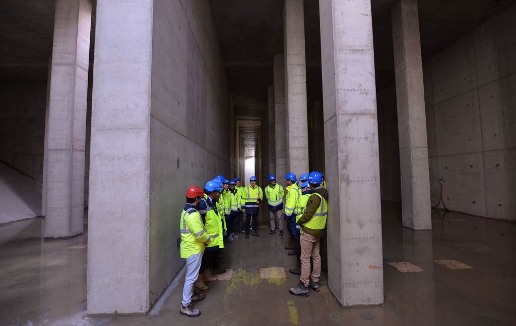
- Area (cooling towers and basins): 6,000 m²
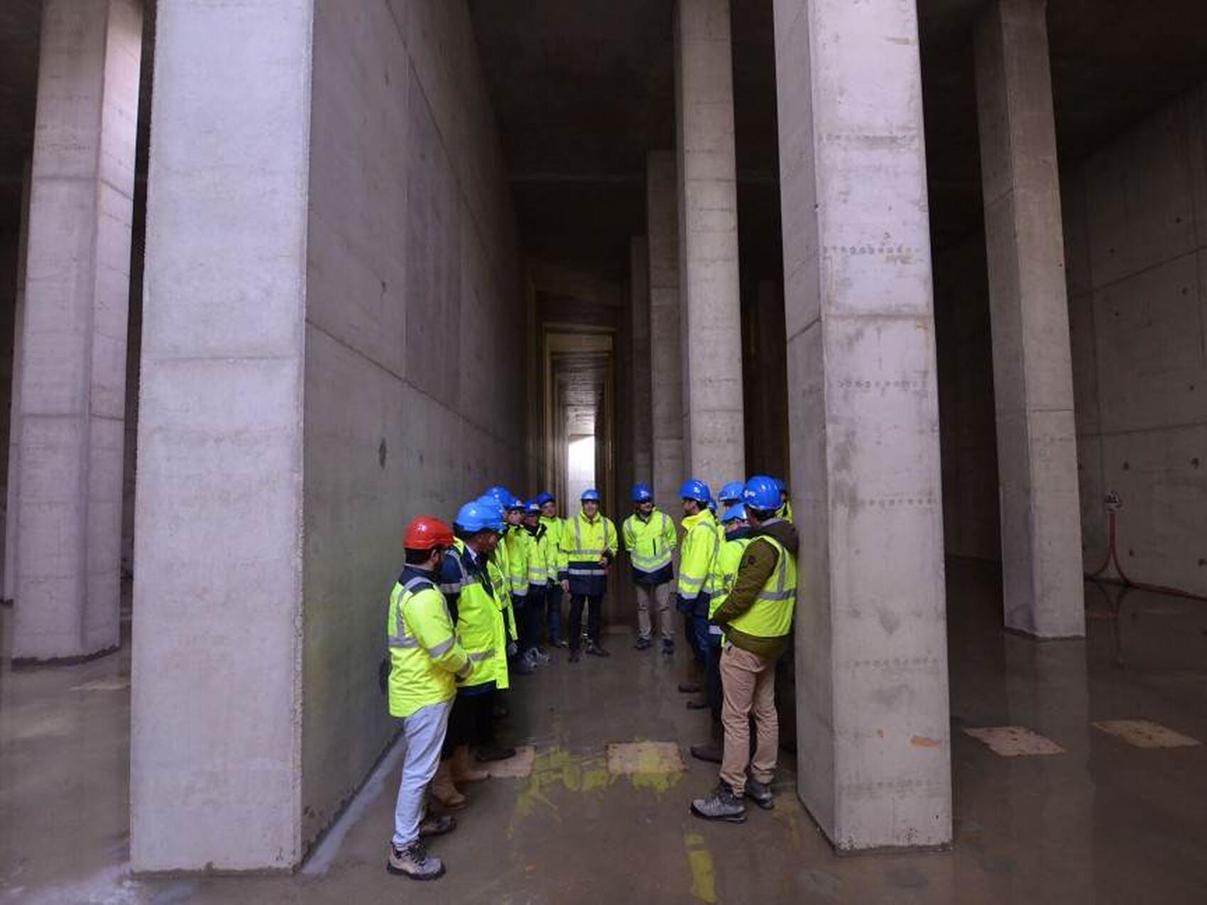
- Total capacity of hot and cold basins: 20,000 m³
- Cooling tower height: 20 m
- Number of cooling tower cells: 10
- Average temperature in hot basin: ≤50 °C
- Maximum total flow rate during operation: 14 m³/s
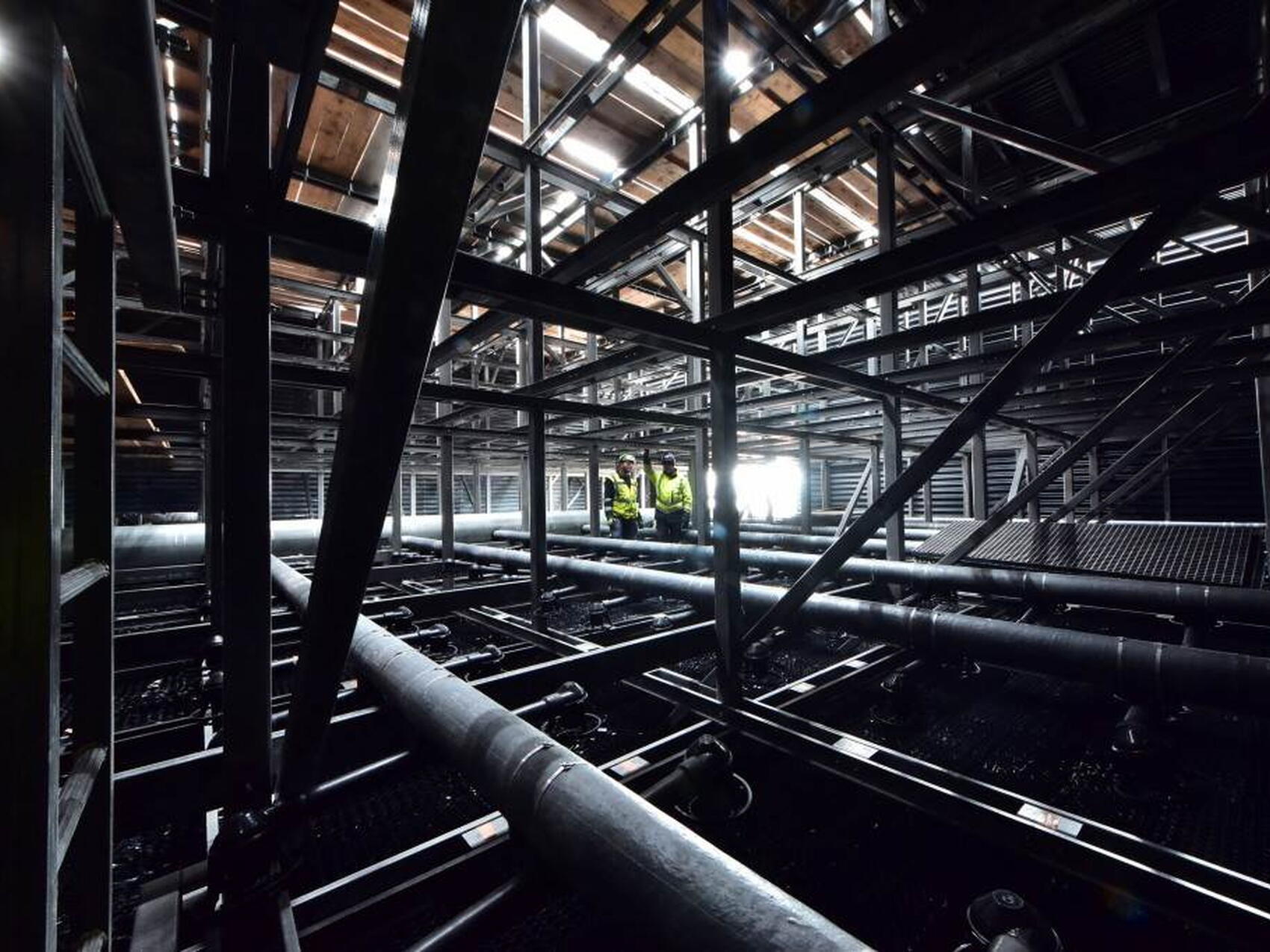
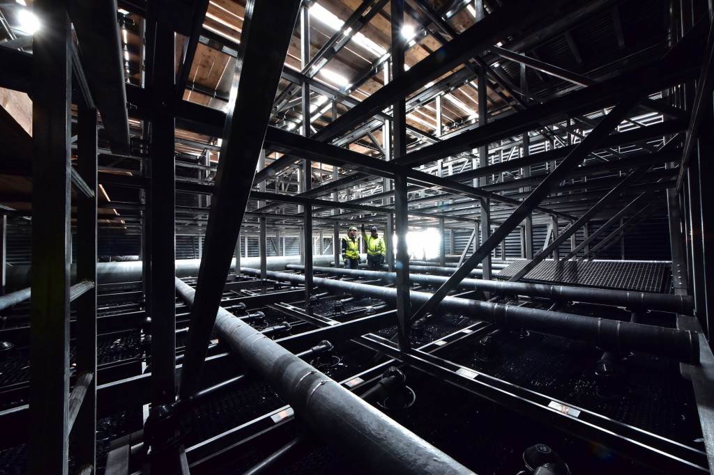
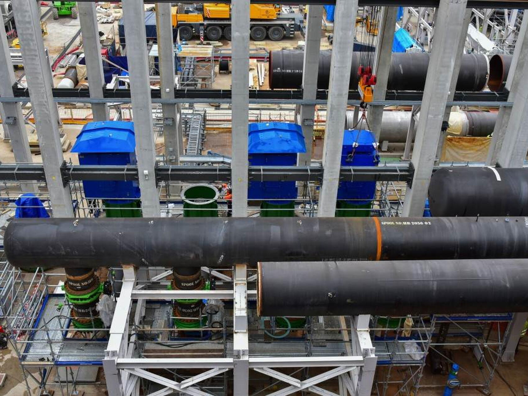
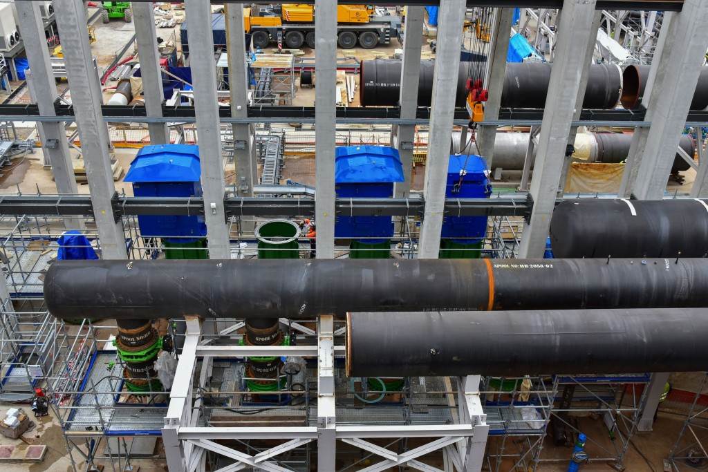
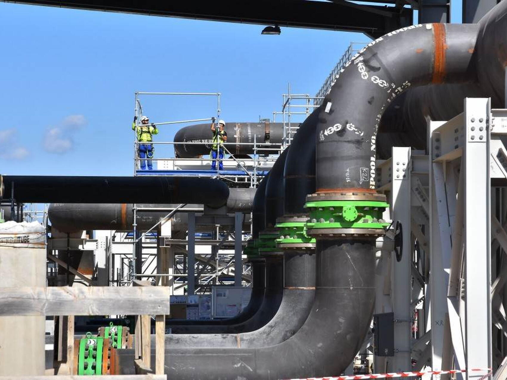
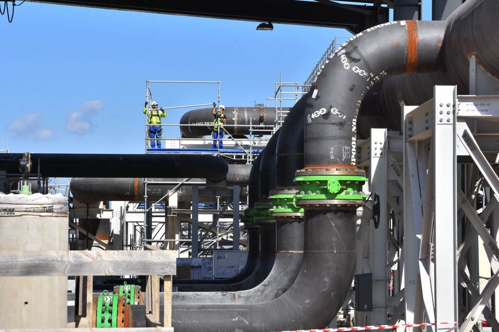
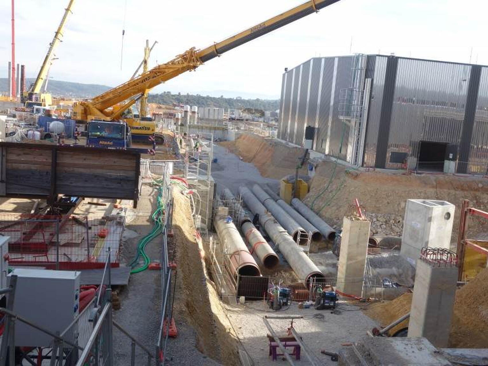
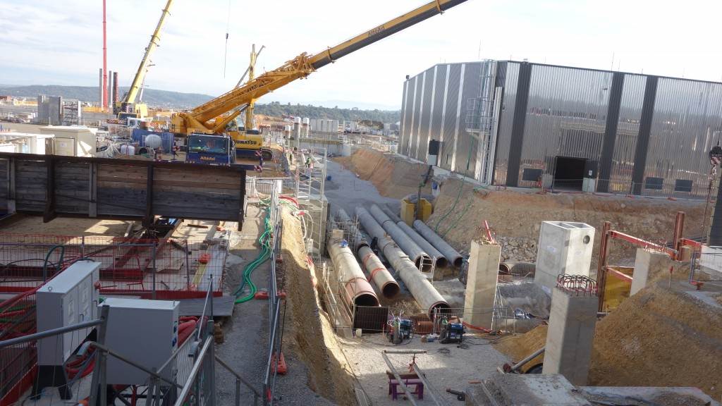
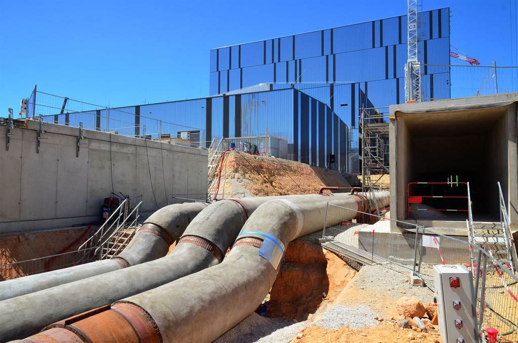
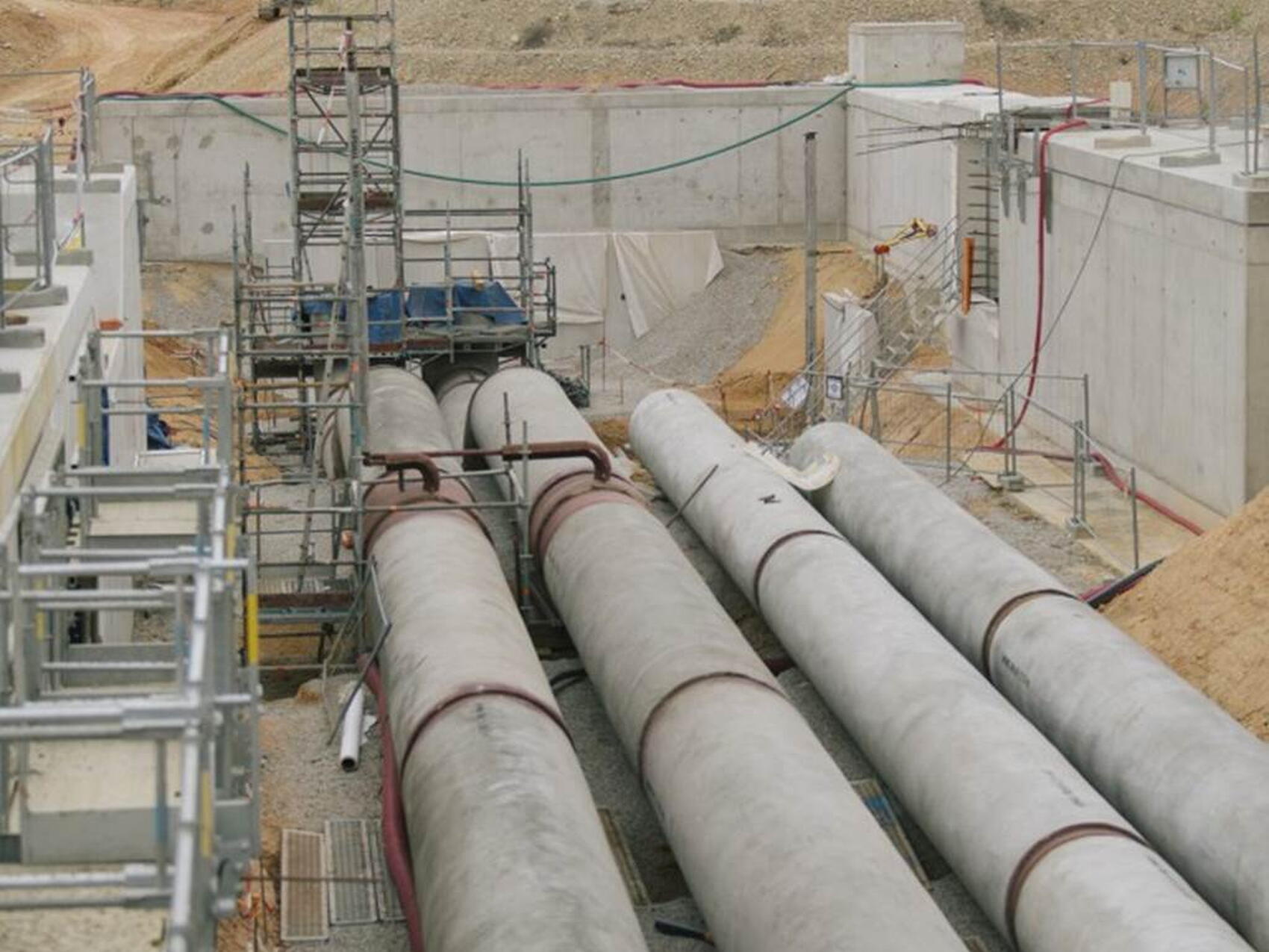
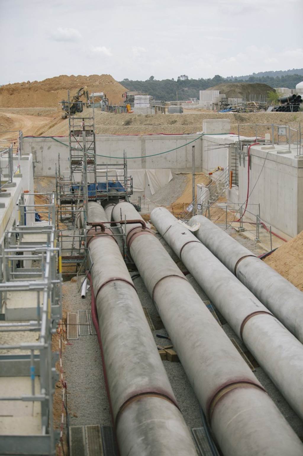
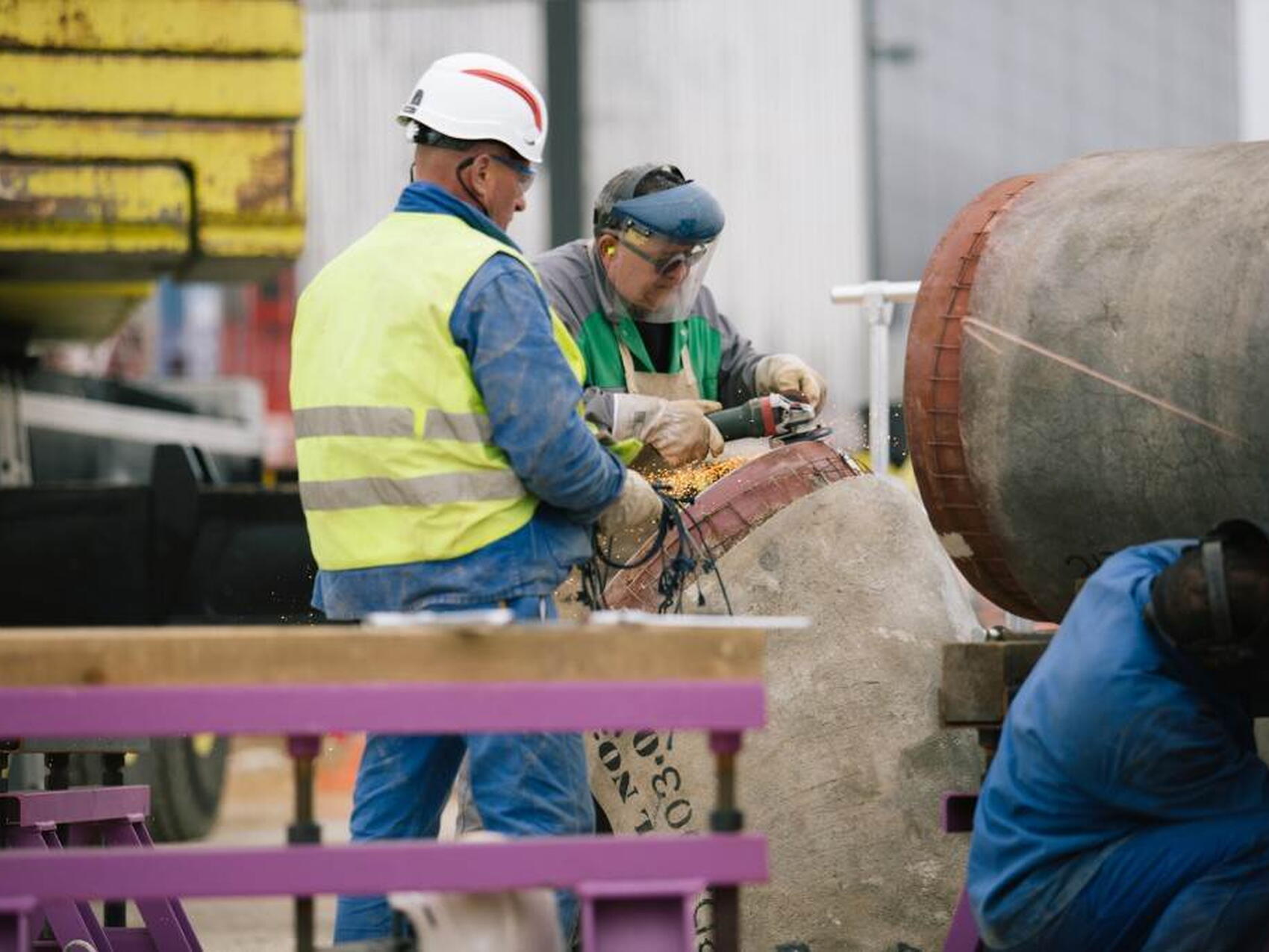
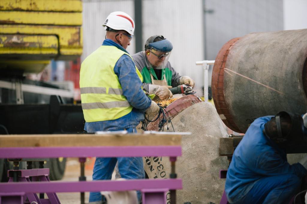
- Nominal diameter of largest piping: 2 m
- Total length of piping in cooling tower area: 5 km
- System status: operational
Photo Gallery