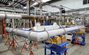
Test bed for ITER's transmission lines completed
11 May 2012
-
Agatha Bardoel, US ITER
Engineers at the Oak Ridge National Laboratory recently completed a new test stand for US ITER to demonstrate that large-scale 12 inch coaxial transmission lines can perform at ITER specifications for the ion cyclotron heating system. Testing to demonstrate continuous 6 MW operations will begin within the next month at ORNL's Energy Systems Test Complex.
"These transmission lines are not off-the-shelf components," Rick Goulding, a scientist in the Plasma Technology and Applications Group at ORNL's Fusion Energy Division said. "They have to carry up to 6 MW each. This is roughly a factor of 3 higher than any radio frequency transmission line that has ever been built for fusion research, and in addition it must operate steady state."
The ion cyclotron resonance ring test stand will also test specific high power components such as gas barriers, phase shifters, coaxial switches, tuning stubs, capacitors and directional couplers. When their tests are completed, the researchers will be able to confirm that the transmission lines, as well as components with moving parts such as capacitors, will be ready to transfer power efficiently from the transmitters into the antennas and finally into the plasma.
"As the plasma particles orbit the magnetic field lines, they can be heated at a frequency that is the same as the orbiting frequency, or is a multiple of that frequency. In this way, you can transfer energy from the radio waves or the microwave field to the ions and to the electrons," explains Goulding.
The ion cyclotron heating system will transfer its energy into the plasma via two launchers that each consist of an array of 24 antenna elements or "current straps." Energy moves through the massive transmission lines to the launcher array. Up to 20 MW of energy from the launchers is transmitted into the plasma through two ports located in the tokamak wall.
The new test bed is shaped like a ring, with water cooling lines laid on the outside of the coax. Inside the ring they have configured a transmission line that simulates the power flow through these lines at ITER. Each section of line consists of an inner core of copper, an outer shell of aluminum, with ceramic and glass insulators to keep the two apart.
The test ring is called "resonant" because, much like giving a push at the right time to a child on a swing makes the swing go higher, the researchers can add power to the ring with an electrical field that matches the electrical field direction and timing inside the line. "Unlike the swing analogy, which is a standing wave, the waves in the ring will be traveling waves, but the resonance rise in the power will be the same," says electrical engineer Phil Pesavento, who helped to develop the test bed. In this way, a transmitter putting out less than 0.5 MW can generate 6 MW of power through the ring.
"We built the resonant ring so that we can duplicate the currents and voltages and the distribution of those that we will actually have in ITER," Goulding said. "We've confirmed this by first making low power measurements that agreed very well with circuit model predictions used in the design of the device. Next, we ran high power, but with no cooling other than natural convection."
"Without cooling, we can run it for two minutes before the copper core conductor reaches the high temperature limit, which is enough time for us to verify that we put 4 MW through it. We looked at how the temperature increases in different parts of the line. The temperature and the electrical measurements agreed with each other, confirming that we had the predicted power flowing through the system."
With their eyes on 6 MW of power, the researchers rebuilt their ring, adding water lines for cooling plus circulating pressurized nitrogen gas between the inner and outer coax conductors. The circulating gas transfers heat from the copper inner conductor to the aluminum outer conductor, where the heat is removed by the water cooling lines. The pressurized nitrogen also improves the high voltage handling capabilities of the transmission lines.
After the system was in place, additional tuning was required. "The holes in the coax where we circulated the gas into and out of the system had detuned the ring too much for it to operate correctly," Pesavento said. "I came up with the idea of using adjustable radiofrequency screens to bring the ring back into resonance." Goulding then designed the necessary modifications to prepare for the 6 MW load testing.
When they test at maximum power, the researchers will circulate gas through the lines, measure the temperatures and verify that the heat transfer is working properly. The goal is to assure that the lines can carry steady state high power that meets ITER's demands, without overheating.
How will they know? "One of the main things we do is to monitor the temperatures both on the inner conductors and on the outer conductors," Goulding said.


