Tricky joints
21 Jan 2014
-
-Paul Libeyre, Central Solenoid and Correction Coil Section leader

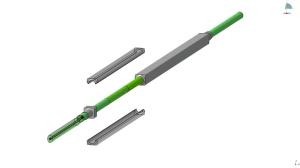
Twin-box joint design for the central solenoid joint sample for SULTAN. Both boxes are soldered on their copper face to an intermediate copper shim.
With the progression of ITER conductor production all over the world, the first lengths of completed conductors are being delivered to coil manufacturers. Although the lengths may extend up to nearly one kilometre, in most cases it will be necessary to connect several lengths together in order to wind the final coils.
To connect adjacent conductor lengths electrically and to connect the coil terminals to the feeder busbars, manufacturers will have to fabricate joints . While standard brazing is generally used in industry to connect regular copper conductor lengths, it has proven far more challenging to join superconducting conductor lengths. Many years of development in laboratories and industry have proved necessary to arrive at acceptable solutions.
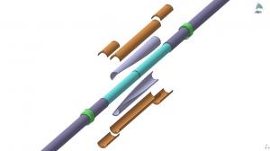
Coaxial joint design. Laced superconducting shells, overlapping both cable ends, are enclosed inside two copper crescents. A stainless steel jacket is installed around.
One of the challenges presented by superconductors is keeping the joint resistance low enough to prevent excessive Joule heating and provide a current transfer, from one conductor to the next, with an as-even-as-possible current distribution among cable strands and within limited space. Another challenge is the cable-in-conduit design (stainless steel jacket around the conductor and an internal flow of supercritical helium) that is common to all ITER conductors. The jacket has to be removed to connect adjacent superconducting cables, while all the while respecting the continuity of the helium flow and tightness of the conduit.
In order to perform final qualification of the joints for ITER conductors, it has been decided to manufacture samples and to measure performance—in particular, joint resistance—in conditions as relevant as possible to tokamak operation. The tests will be performed at the SULTAN facility in Switzerland.

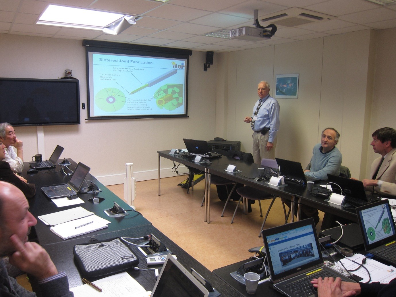
N. Martovetsky, from US ITER, presents the design of the central solenoid joint sample to the review panel chaired by P. Bruzzone (foreground, left) on 18 December 2013.
The design of the joints connecting the ITER correction coils with the feeder busbars relies on the use of the overlap twin-box joint concept (see Fig. 1), initially developed in the laboratories of the French CEA and then used in the Toroidal Field Model Coil (TFMC) built by Europe during the ITER Engineering Design Activities phase. In this design, each conductor end is enclosed inside a bimetallic stainless steel-copper box and adjacent box copper faces are soldered with each other. Low resistance can be achieved, in the order of a few nanoohms, but at the expense of a large consumption of space since locally two conductors are overlapping.
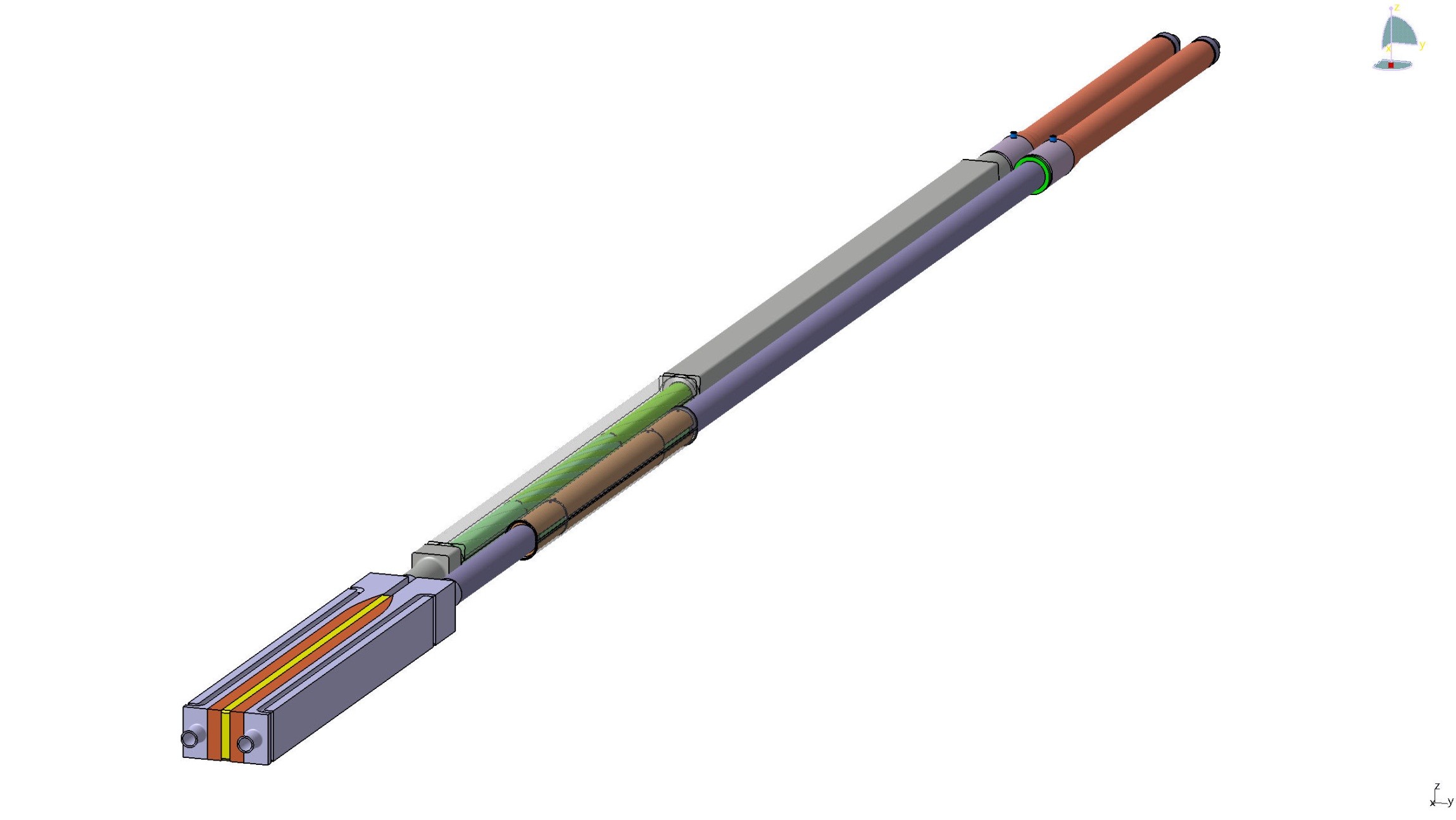
Due to the specific space requirements of the central solenoid, the US Domestic Agency has developed two new types of joints, both fitting within the regular space of a single conductor: a splice joint (Fig. 4), connecting conductor lengths inside a module; and a coaxial joint (Fig. 2), connecting coil terminals to busbar extensions running along the coil outer diameter. The busbar extensions are themselves connected to the feeder busbars by classical twin-box joints.

Splice joint connecting conductor lengths inside central solenoid modules. After the jacket is removed at both cable ends, the cables are interleaved at the level of each sub-cable and jacket shells are installed around and welded to the conductor jacket.
Two final design reviews were conducted in late 2013 to review the designs of a correction coil joint sample (to be manufactured by correction coil manufacturer ASIPP, China), and the design of a central solenoid joint sample (to be manufactured by central solenoid modules manufacturer General Atomics, US). Both samples are planned to be manufactured and tested in 2014.
For both the correction coil and central solenoid joint designs, the review panel provided a positive recommendation on the presented designs and on the proposed testing programs, paving the way to the start of their manufacture early 2014.