Subscribe options

Select your newsletters:

Please enter your email address:

@

Your email address will only be used for the purpose of sending you the ITER Organization publication(s) that you have requested. ITER Organization will not transfer your email address or other personal data to any other party or use it for commercial purposes.

If you change your mind, you can easily unsubscribe by clicking the unsubscribe option at the bottom of an email you've received from ITER Organization.

For more information, see our Privacy policy.

News & Media

Latest ITER Newsline

  • Vacuum components | Shake, rattle, and... qualify!

    A public-private testing partnership certified that ITER's vacuum components can withstand major seismic events. Making sure the ITER tokamak will be safe in th [...]

    Read more

  • Feeders | Delivering the essentials

    Like a circle of giant syringes all pointing inward, the feeders transport and deliver the essentials to the 10,000-tonne ITER magnet system—that is, electrical [...]

    Read more

  • Image of the week | It's FAB season

    It's FAB season at ITER. Like every year since 2008, the Financial Audit Board (FAB) will proceed with a meticulous audit of the project's finances, siftin [...]

    Read more

  • Disruption mitigation | Final design review is a major step forward

    The generations of physicists, engineers, technicians and other specialists who have worked in nuclear fusion share a common goal, dedication and responsibility [...]

    Read more

  • Image of the week | Like grasping a bowl of cereal

    Contrary to the vast majority of ITER machine components, the modules that form the central solenoid cannot be lifted by way of hooks and attachments. The 110-t [...]

    Read more

Of Interest

See archived entries

Optic sensors

Testing the resistance to radiation

Inside the ITER machine, the divertor and the blanket will be equipped with more than 1,000 fibre optic sensors for recording temperature, strain, displacement and acceleration—important feedback to estimating the health and residual lifetime of these components that are located so near the plasma. Sensor prototypes designed by the ITER Organization have already been tested thermally, mechanically and optically; now—thanks to the first Implementing Agreement of the ITER Organization-Kazakhstan Cooperation Agreement—they will soon be tested for radiation resistance.

ITER will use a special type of optical fibre—the non-standard FBG fibre—to relay important information on the health of the plasma-facing components. Sensor prototypes and fibres are about to be tested for neutron resistance in two Kazakh research reactors under the terms of an technical cooperation Implementing Agreement signed in April. (Click to view larger version...)
ITER will use a special type of optical fibre—the non-standard FBG fibre—to relay important information on the health of the plasma-facing components. Sensor prototypes and fibres are about to be tested for neutron resistance in two Kazakh research reactors under the terms of an technical cooperation Implementing Agreement signed in April.


A large number of sensors on the divertor and blanket will tell engineers how these internal machine components are doing under the stress of operation.

Devices no larger than a postage stamp will be mounted on 3 of the 54 divertor cassettes and on 20 of the 440 blanket shield blocks installed inside the machine. These highly sensitive instruments—formed from steel-plate sensors embedded with neutron-resistant optical fibres—will be capable of measuring temperature, strain, displacement, or even the smallest vibration, and of transmitting the information to software for analysis.

"The optical operational instrumentation for the internal components is based on the analysis of transmission of light," explains Sergey Bender, instrumentation engineer in the Divertor Section. "As temperature or strain increases in the internal components of the machine, there is a corresponding shift in light wavelengths that can be measured and interpreted."

Optical fibre technology is attractive for fusion applications, in particular thanks to its immunity to the rapid and large variation of electromagnetic fields during plasma disruptions—exactly the moment when there is a major need for measurements. 

An example of an ITER FBG optical sensor that will be tested in Kazakhstan (size: 15 x 15 x 0.8 mm). A special technique has been developed in order to embed the specialized fibres in the sensor. (Click to view larger version...)
An example of an ITER FBG optical sensor that will be tested in Kazakhstan (size: 15 x 15 x 0.8 mm). A special technique has been developed in order to embed the specialized fibres in the sensor.
Neutrons can darken optical fibres over time, however, resulting in a reduction of their reflective index and hence their ability to transmit information. To overcome this drawback, ITER's instruments will use a special type of non-standard FBG optical fibre (for Fiber Bragg Grating) that is neutron-resistant. FBG measurements are based on wavelength shifts rather than on the amplitude of the optical wave, which is impaired by the reduction of reflective index.

According to Bender, the neutron immunity of this particular type of fibre makes it an essential feature in monitoring the internal components.

Under the first Implementing Agreement of the Cooperation Agreement that was signed between the ITER Organization and the National Nuclear Center of the Republic of Kazakhstan last year, samples of sensors and optical fibres for ITER operational instrumentation will be tested for neutron resistance in Kazakh research reactors to confirm all design assumptions and to clear the way for industrial manufacturing.

Two test phases are planned:
  • Several four-hour irradiation campaigns at the IVG -1M research reactor in Kurchatov to test how the operational instrumentation works under different temperatures and dose rates and to define the characteristics of the samples (fibre length, temperature) for the second campaign.
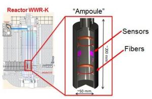
  • A 23-day campaign at the WWR-K research reactor in Almaty, under fully ITER-relevant neutronic fluence (up to 1020 n/cm2, for an energy higher than 0.1 MeV). (Neutronic fluence is defined as the number of neutrons per unity of surface cumulated during a given time.)
"What we are looking for from these irradiation tests, is a final demonstration that the optical FBG sensors, as developed by the ITER Organization, are substantially immune to neutron damage in terms of accuracy and stability of measurements. The neutronic fluence attainable in the WWR-K reactor is similar to the one expected on the surface of ITER's internal components at the end of operations. This is the key capability proposed by our Kazakh colleagues, and it makes the tests highly interesting to us," explains Frédéric Escourbiac who, as Divertor Section Leader, is in charge of the operational instrumentation for the internal components.

Kazakh scientists are developing and manufacturing a special ''ampoule''—a 20-centimetre canister containing the sensors and optical fibres—that will be inserted into the WWR-K reactor. (Click to view larger version...)
Kazakh scientists are developing and manufacturing a special ''ampoule''—a 20-centimetre canister containing the sensors and optical fibres—that will be inserted into the WWR-K reactor.
Under the terms of the collaboration, the ITER team has ordered a small amount of radiation-resistant fibres from different manufacturers, had them "marked" with lasers to print the FGB feature¹, and created the sensors. Kazakh colleagues will prepare a special canister called an "ampoule" (see photo, left) with these sensors to be tested during the irradiation campaigns. The Kazakh team is also responsible for campaign implementation as well as the analysis of all results.

The first radiation-resistance tests are planned in November this year after six months of preparation to manufacture and prepare the samples.

¹Fiber Bragg gratings are created by using a laser source to "inscribe" or "write" a systematic interference pattern along the optical fibre. The "marks" reflect narrow bandwidths of light, which respond to changes in temperature or strain by shifting.


return to the latest published articles