This was a perfect challenge for the ITER Makers. But time was of the essence, since the next inspection was due in just four days (weekend included).
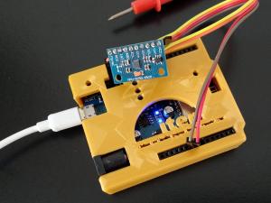
Quick, a solution! Romain Bourgue, the co-founder of the ITER Makers group, identified a solution: a small position sensor that would integrate a gyroscope, a compass and an accelerometer. This component, similar to the device used in smartphones, would be attached to the end of the endoscope and transmit position information to an
Arduino microcontroller. The Arduino would in turn send output to a computer monitor, where a 3D model of the endoscope would rotate and show users the live position of the tool.
Working together during a few fruitful lunchbreaks and a weekend, the group soon had a working prototype, complete with a custom casing fabricated with the Makers' 3D printer.
Now to the real thing! The next steps involved moving from prototype to the real thing. Knowing that the endoscope cable is 5 metres, the Makers soldered the sensor to a 10-metre cable and re-verified its functionality. The sensor then needed to be attached securely to the camera of the endoscope, using heat shrink tubing at the endoscope tip and cable ties to complete the installation.
The inspection took place at the nearby
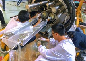
MIFI workshop at the French Alternative Energies and Atomic Energy Commission (CEA) research centre, where the first magnet feeder component is currently stored. With the gyroscopic information telling the endoscope user the exact positioning of the instrument, the inspection was a success.
Romain Bourgue, IT Security & Policy Responsible Officer; Jaromir Farek, Magnet Auxiliaries Structural Specialist; Nuno Pedrosa, Non-Destructive Testing Engineer; Jean Revel, Instrumentation & Control Engineer; and Wan Lijun, Superconducting Auxiliaries Engineer all contributed to the project.


