Cooling system
From river to droplets and mist
27 Jan 2020
-
R.A.
A subterranean river runs through the ITER installation. Rushing through 60 kilometres of piping, passing through dozens of pumps, filters and heat exchangers at a rate of up to 14 cubic metres per second, its flow is more than half that of the nearby Verdon River. This ramified network is tasked with cooling and evacuating the heat generated by ITER operation—one main loop designed for the Tokamak proper, the other for the installation's auxiliary systems.
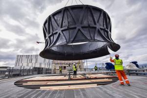
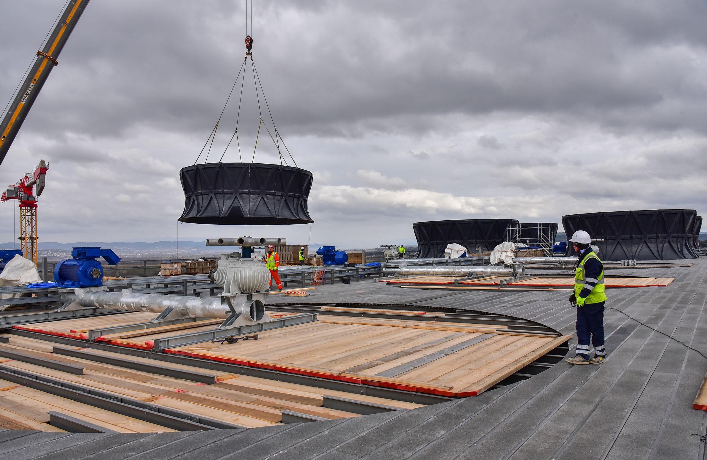
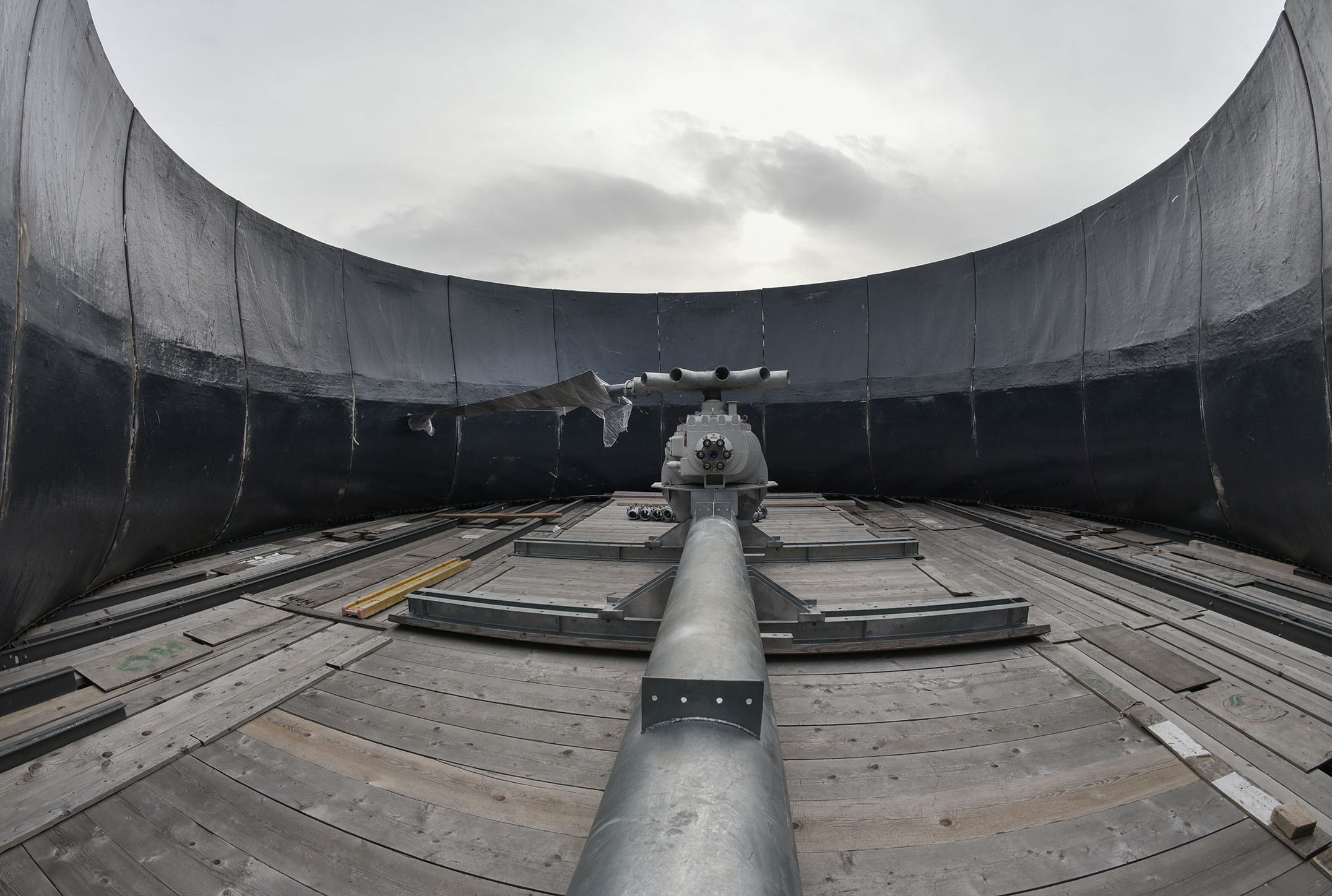
Each cooling cell is topped by "fan cylinder" hosting a twelve-blade fan (not yet installed) that induces an upward draft. Seven such cylinders have now been installed; the remaining three are being assembled and will be lifted in the coming weeks.
Cooling this considerable flux of water requires a massive installation based on simple principles: heat exchange, evaporation and re-condensation.
Evaporation cools—we experience it on a daily basis when we step out of the shower. As water molecules transition from liquid to gaseous (vapour), they draw heat from the skin and generate a cold sensation throughout the body. This is one of the principles at work in the ten cooling cells of the heat rejection zone, a 6,000-square-metre facility located at the north end of the ITER platform.
A squat black building accommodates the main feature of the ITER heat rejection system: ten cooling cells that act like the familiar concrete cooling towers of an industrial power plant, whether thermal or nuclear. But whereas the upward airstream that accelerates the evaporation process occurs naturally in a conventional cooling tower, it is induced by large fans in the ITER cooling cells.
The advantages of induced draft cooling towers are size, cost and flexibility: their footprint is much smaller than that of a concrete cooling tower, their construction cost is significantly lower, and their flexibility is well adapted to the intermittent nature of ITER operation.
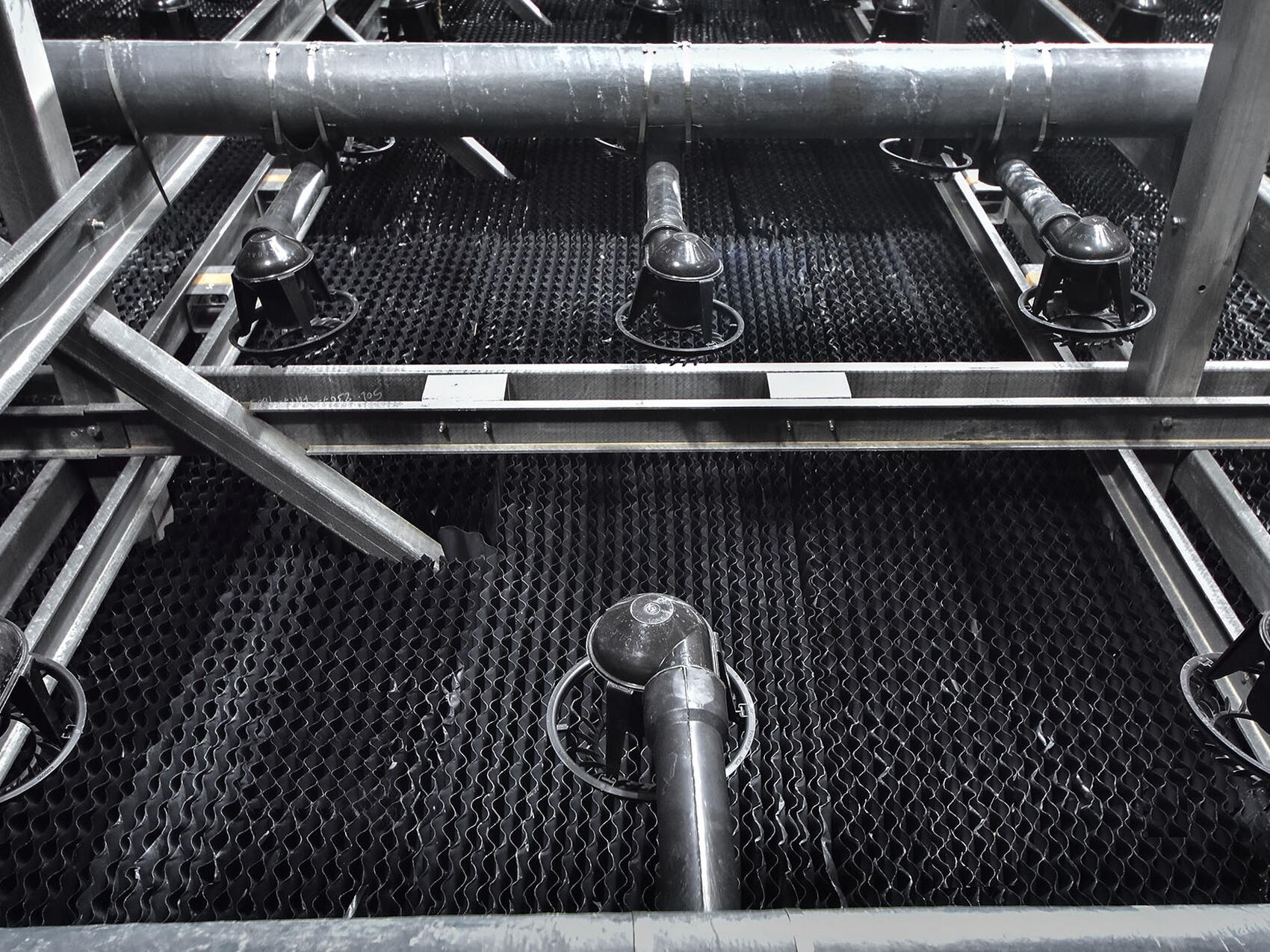
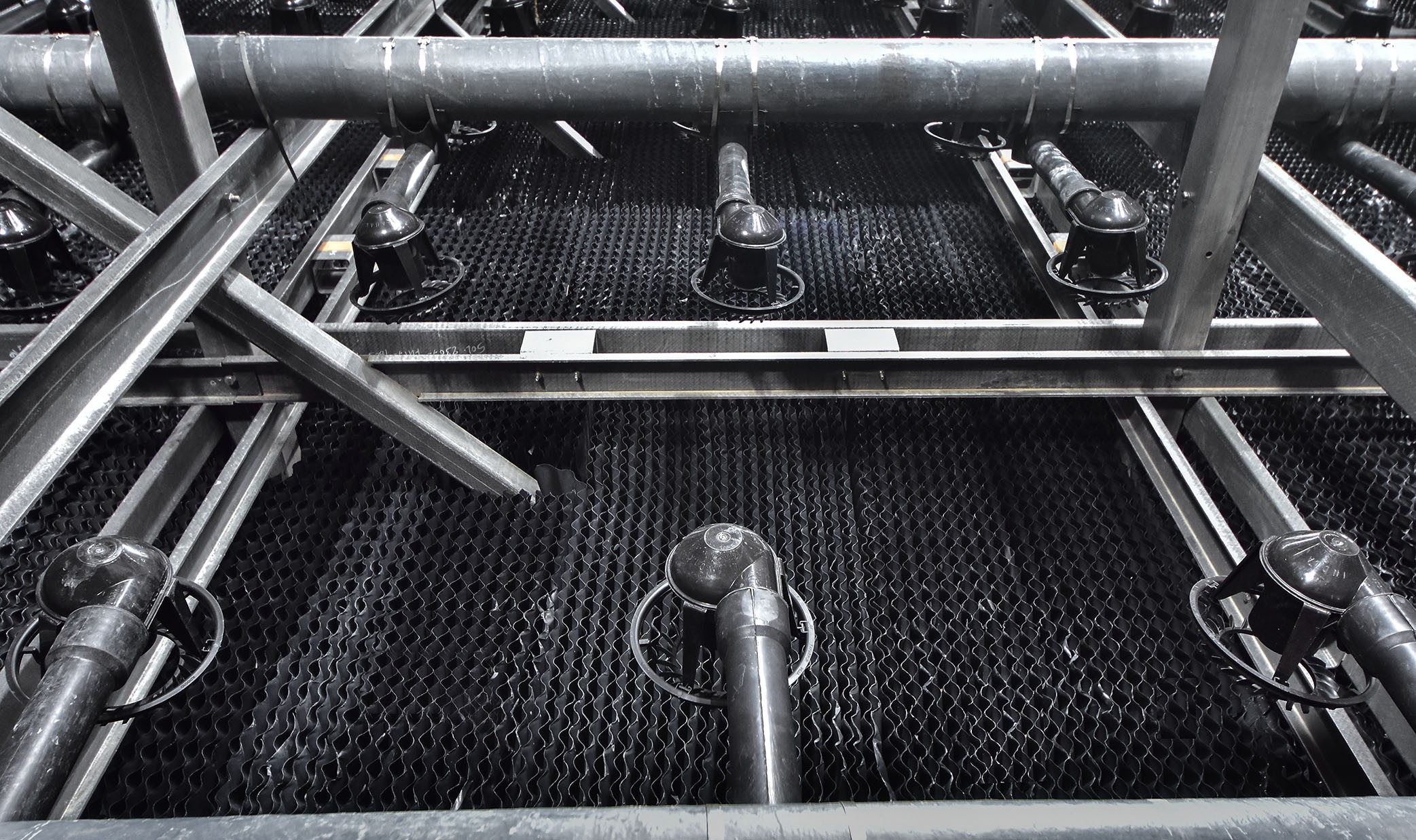
The efficiency of the cooling process depends of the surface through which the heat is exchanged. Similar to cooling fluid in a car engine passing through the honeycomb structure of the radiator, hot water entering the cooling cells¹ is sprinkled by a set of 4,540 spray nozzles into a stack of corrugated plastic sheets called a "fill pack." If unfolded, the total exchange surface provided by the fill pack would be on the order of 704,000 square metres, the equivalent of some 70 football fields.
Efficiency also depends on how long the droplets remain in contact with the fill-pack exchange surface. Left to the natural effect of gravity, the duration of contact would not be sufficient and droplets falling from the spray nozzles would not have enough time to cool to the required temperature. To remedy this, the droplets' fall is slowed by the upward draft induced by the large fan on top of every cell.
This upward draft creates a drag force, however, that could cause the droplets to scatter and be lost. And water—in the ITER heat rejection system like everywhere else—should not be wasted.
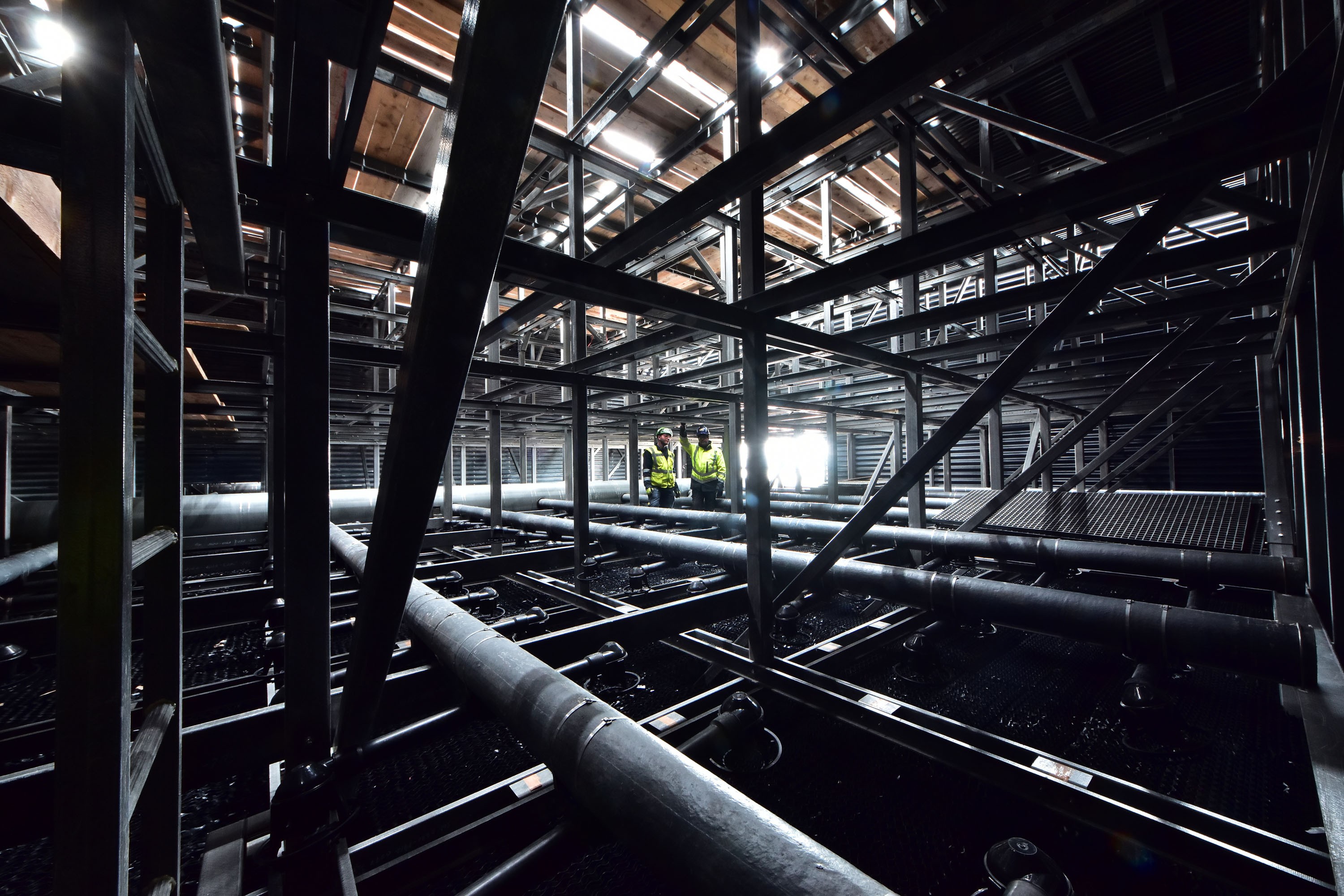
Inside each cooling cell, stacked layers of millimetre-thick corrugated plastic sheet ("fill pack") act like the honeycomb structure of a car radiator. (Look closely at the black "floor.")
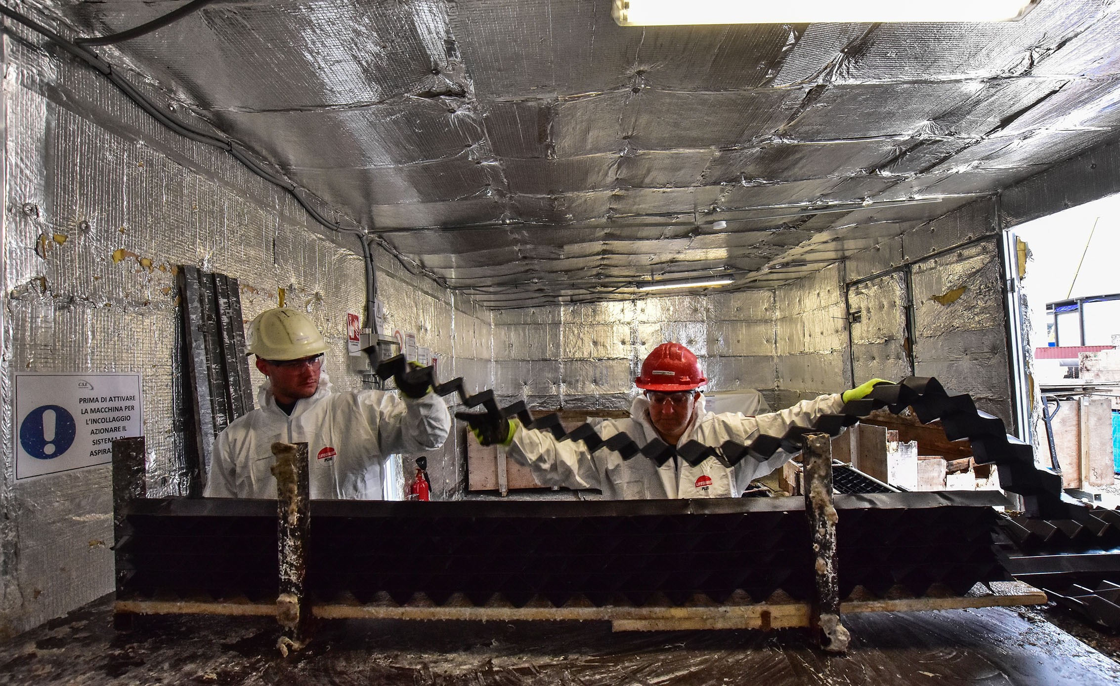
The droplets and mist lifted by the draft must be recaptured to bring the "drift losses" to an acceptable level. Thousands of "drift eliminator" units at the top of each cell, above the spray nozzles and the 1.6-metre-thick stacked fill pack, provide a dense, zigzagging labyrinth (see photo) that causes droplets to change direction, lose velocity and fall back into the cooling tower, significantly reducing the drift losses.
¹ Pumped from the heat rejection system's hot basin (which acts as a heat dump) and from other plant services, the water enters the cooling cells at a temperature of 43 °C.
At the end of the process the water, now considerably cooler than when it entered the cells (27 °C), falls into the cold basin under the towers. From there, it is transported by huge vertical pumps to the different heat exchangers of the system, where it goes back to cooling the plant systems and the Tokamak secondary loop.
And the cycle repeats itself endlessly, extracting and rejecting the massive quantity of heat generated by the tokamak, its auxiliaries and the installation's plant systems. At full power the combined load that needs to be evacuated is of the order of one gigawatt, approximately half of it generated by the heat from the fusion reaction collected by the plasma-facing wall inside the vacuum vessel.
If ITER were an industrial fusion plant, the heat in the plasma-facing wall would be converted into electricity by way of steam generators, turbines and alternators. But as a research installation—with a non-steady-state experimental device—installing electricity-generating equipment would not have made sense.
On the roof of the squat black building that accommodates the cooling cells, seven out of ten funnel-like fan cylinders are in place. The remaining three are being assembled and will be lifted in the coming weeks. Inside the cells, 80 percent of the fill pack units are now stacked together under the spray nozzles, and about half of the 4,000 drift eliminator sheets are glued together and ready to be positioned above the fill packs, under the large fans.
¹ Pumped from the heat rejection system's hot basin (which acts as a heat dump) and from other plant services, the water enters the cooling cells at a temperature of 43 °C.
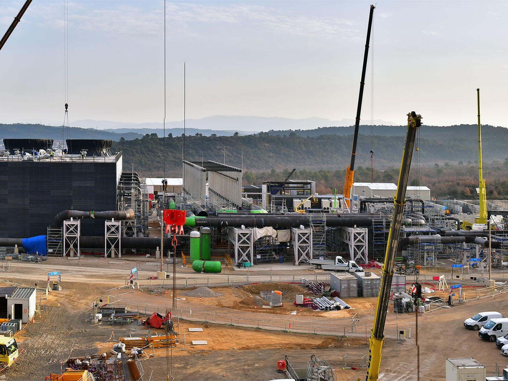
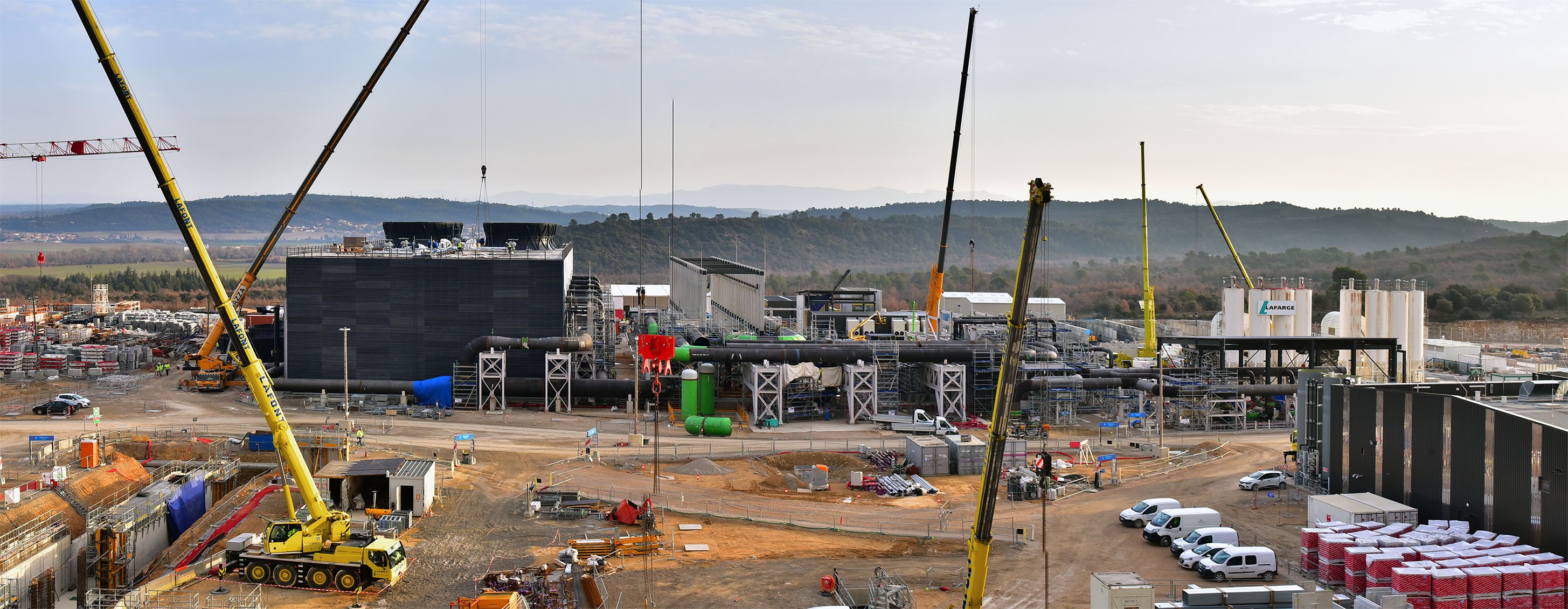
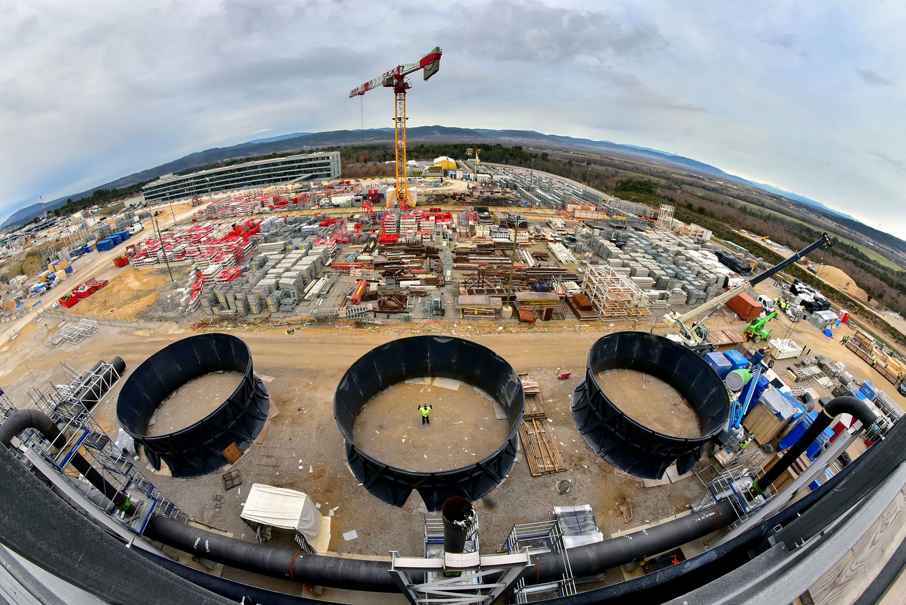
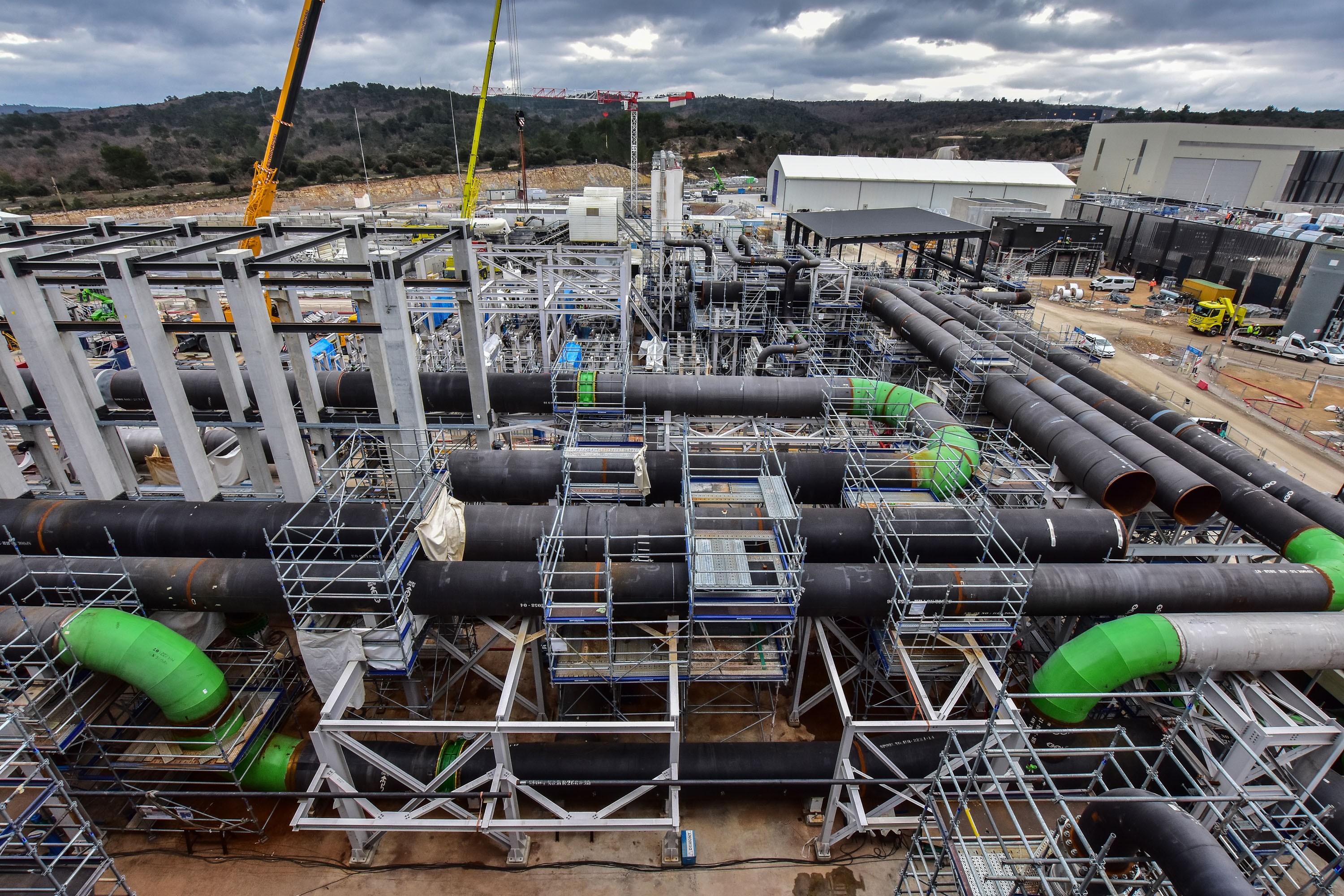
It all ends up here, in the 6,000-square-metre heat rejection zone. The squat black building to the left hosts the 10 cooling cells that are tasked with evacuating the heat generated by operation; to the right, a complex network of piping, pumps and heat exchangers connects the installation's cooling loops to the cells and the underground hot and cold basins.
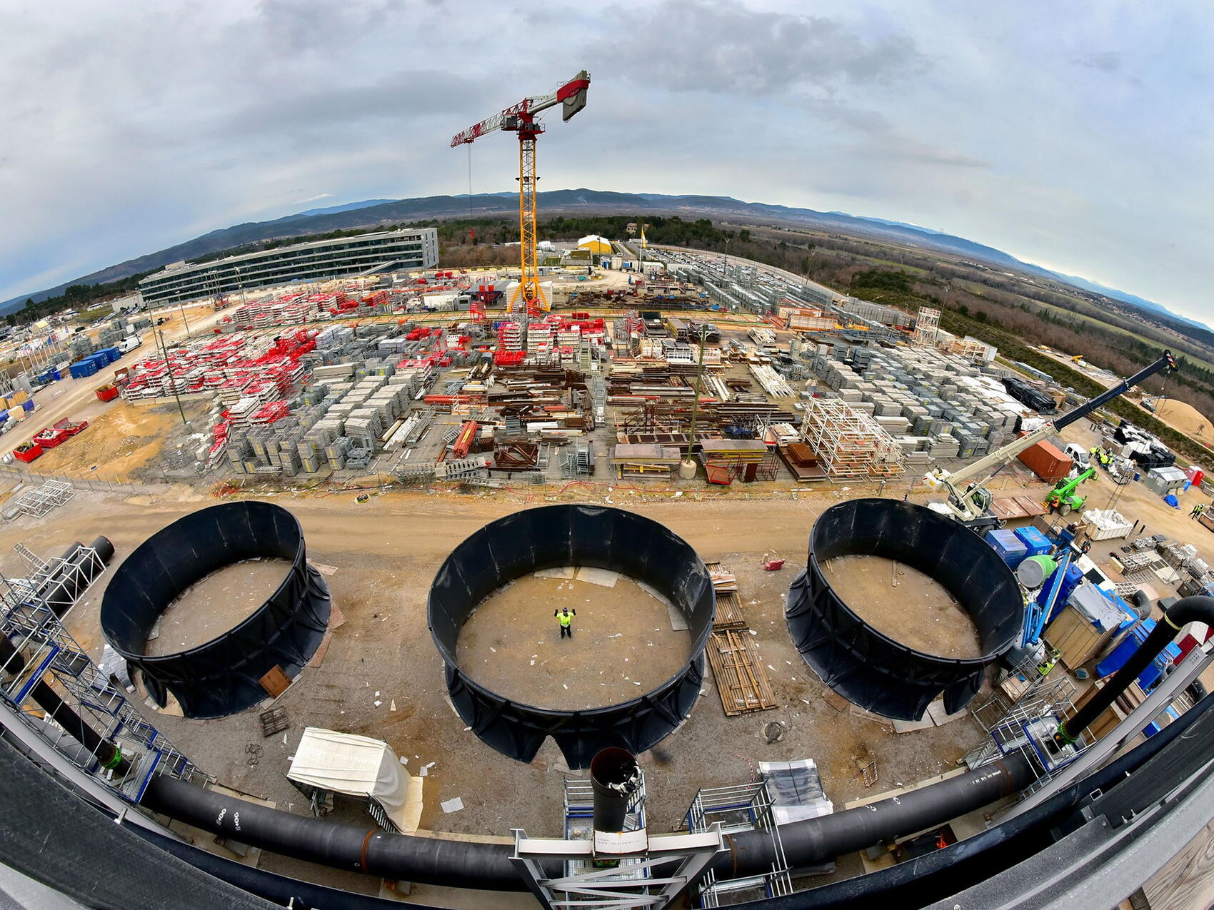
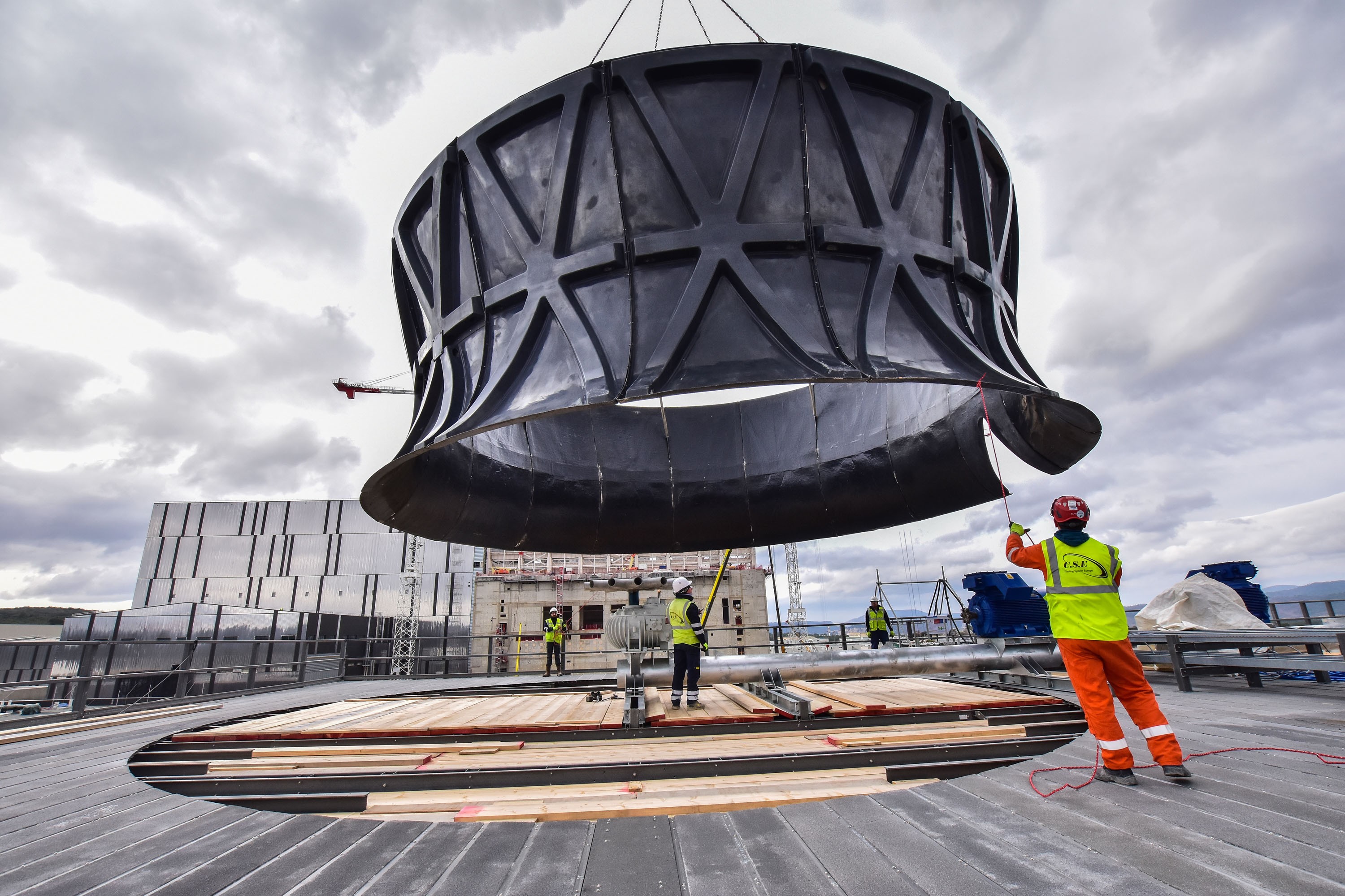
Three "fan cylinders" made of fibre-reinforced plastic are ready to be lifted and installed on the roof. Each one measures more than 11 metres in diameter and weighs approximately 3 tonnes.
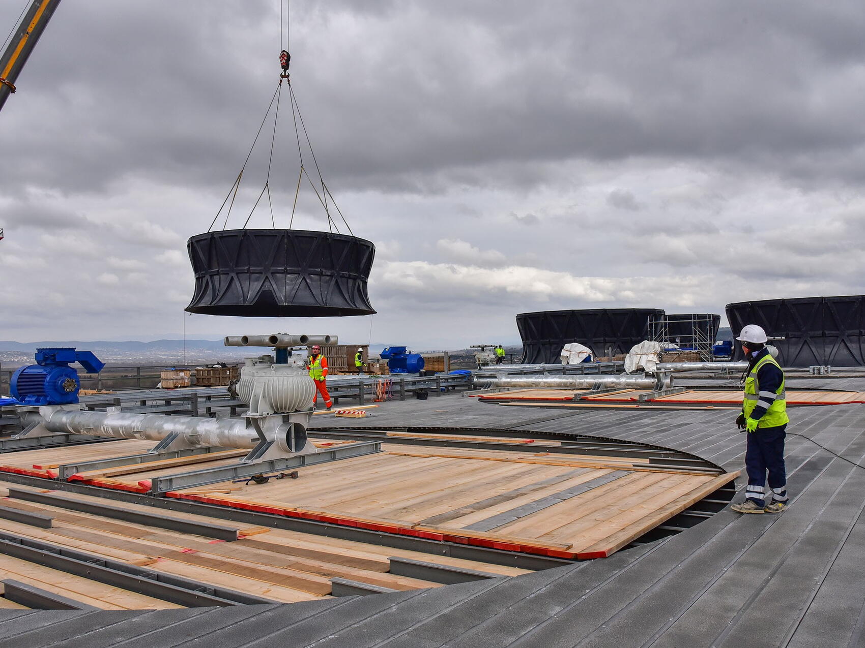
A 3-tonne fan cylinder is being lifted into its final position above the cooling cell. The fan rotor (grey), connected through a shaft to a 170 kW electrical motor (blue), is ready to be fitted with twelve 5-metre long plastic blades.
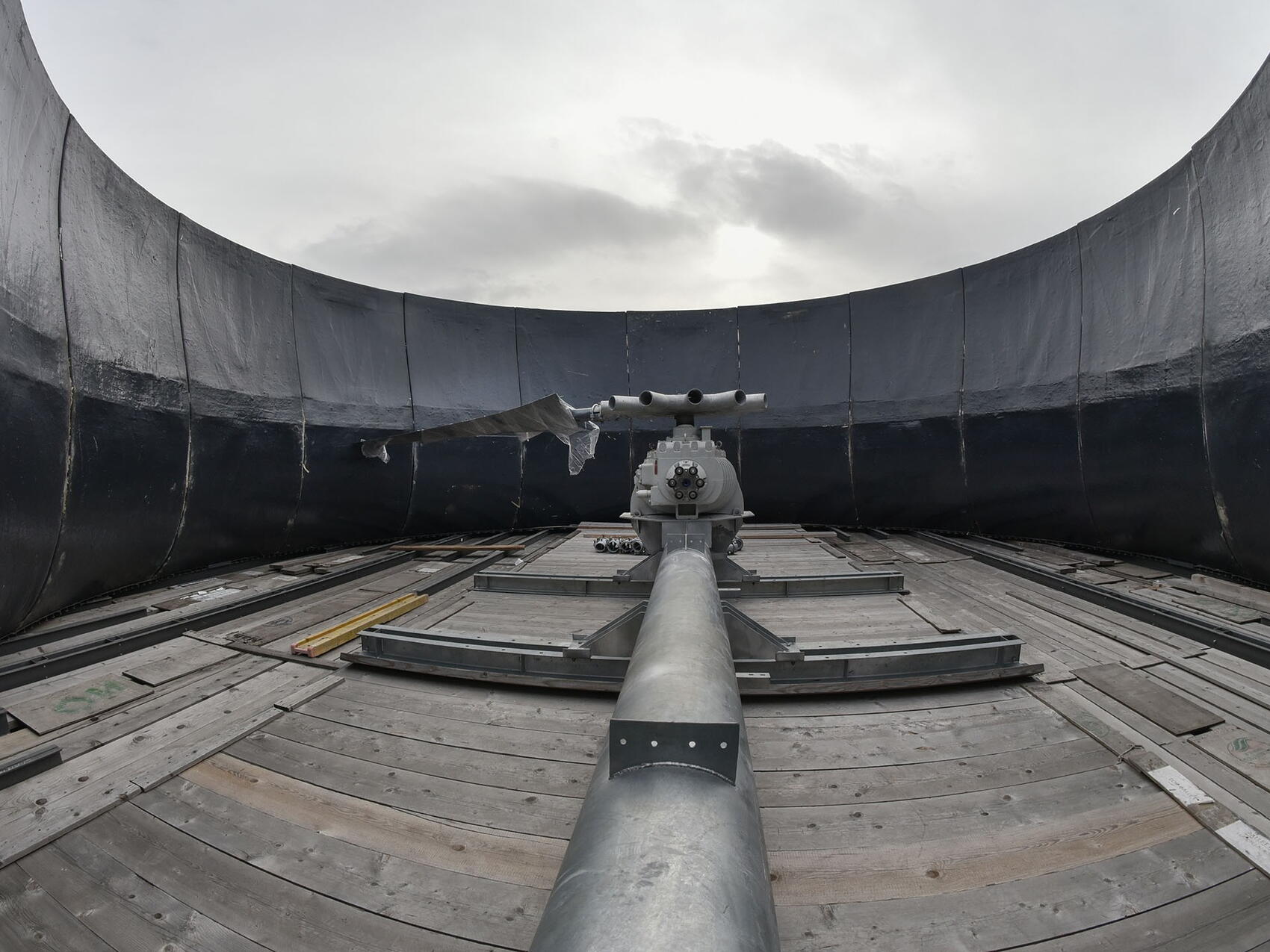
Rotating at 92 rpm, a large twelve-blade fan on top of each cell induces the upward draft that optimizes the cooling process. Here, inside a newly installed fan cylinder, the fan's rotor has just been equipped with its first blade.
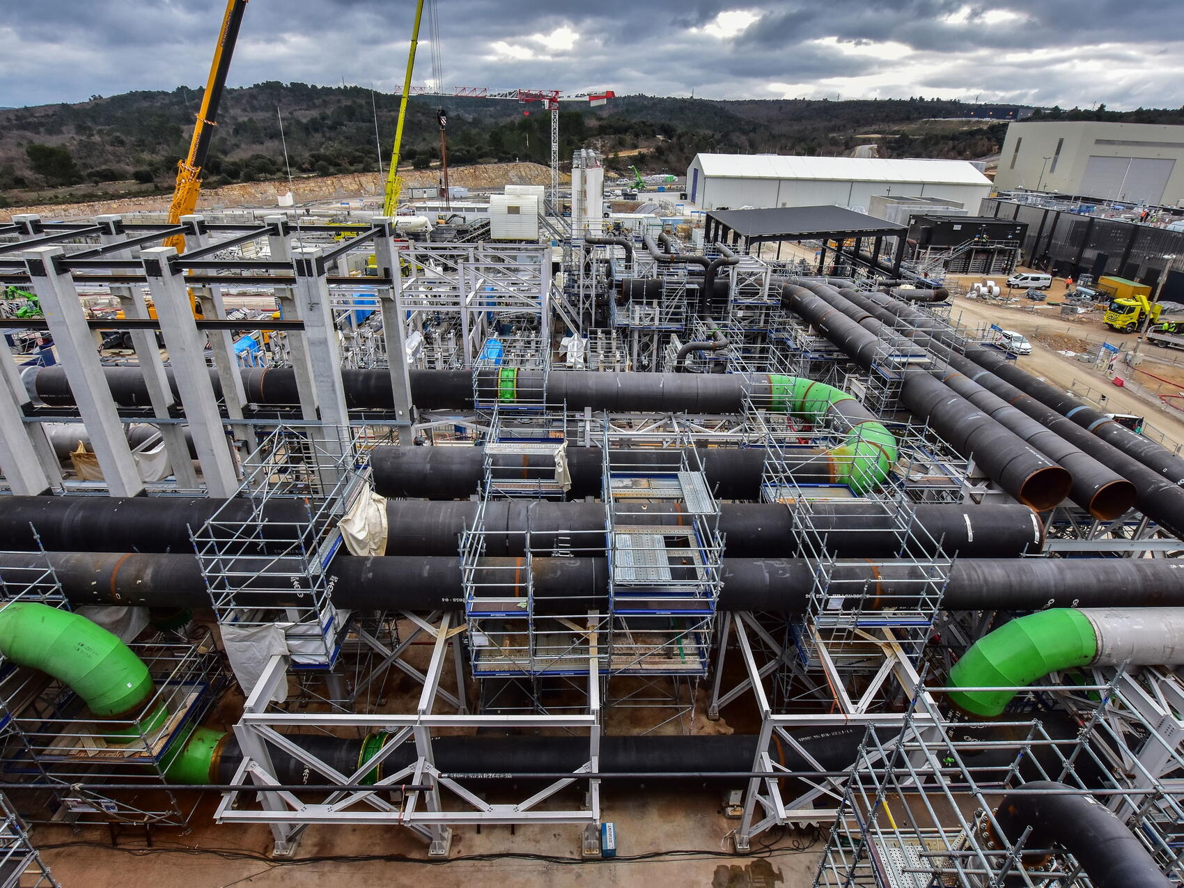
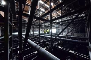
Cooling water flows through approximately 5 kilometres of piping and 17 heat exchangers inside the heat rejection zone. At full power, the combined load that needs to be evacuated is on the order of one gigawatt, approximately half generated by the burning plasma inside the Tokamak.
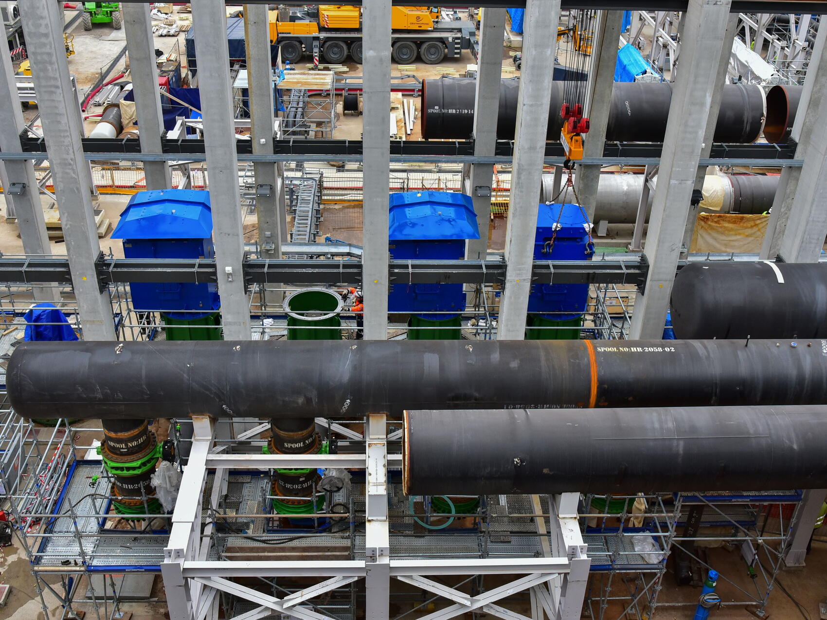
Thirteen large vertical turbine pumps (in blue), each one powered by a 870 kW motor and capable of moving 10 tonnes of water per second, circulate water throughout the heat rejection system.
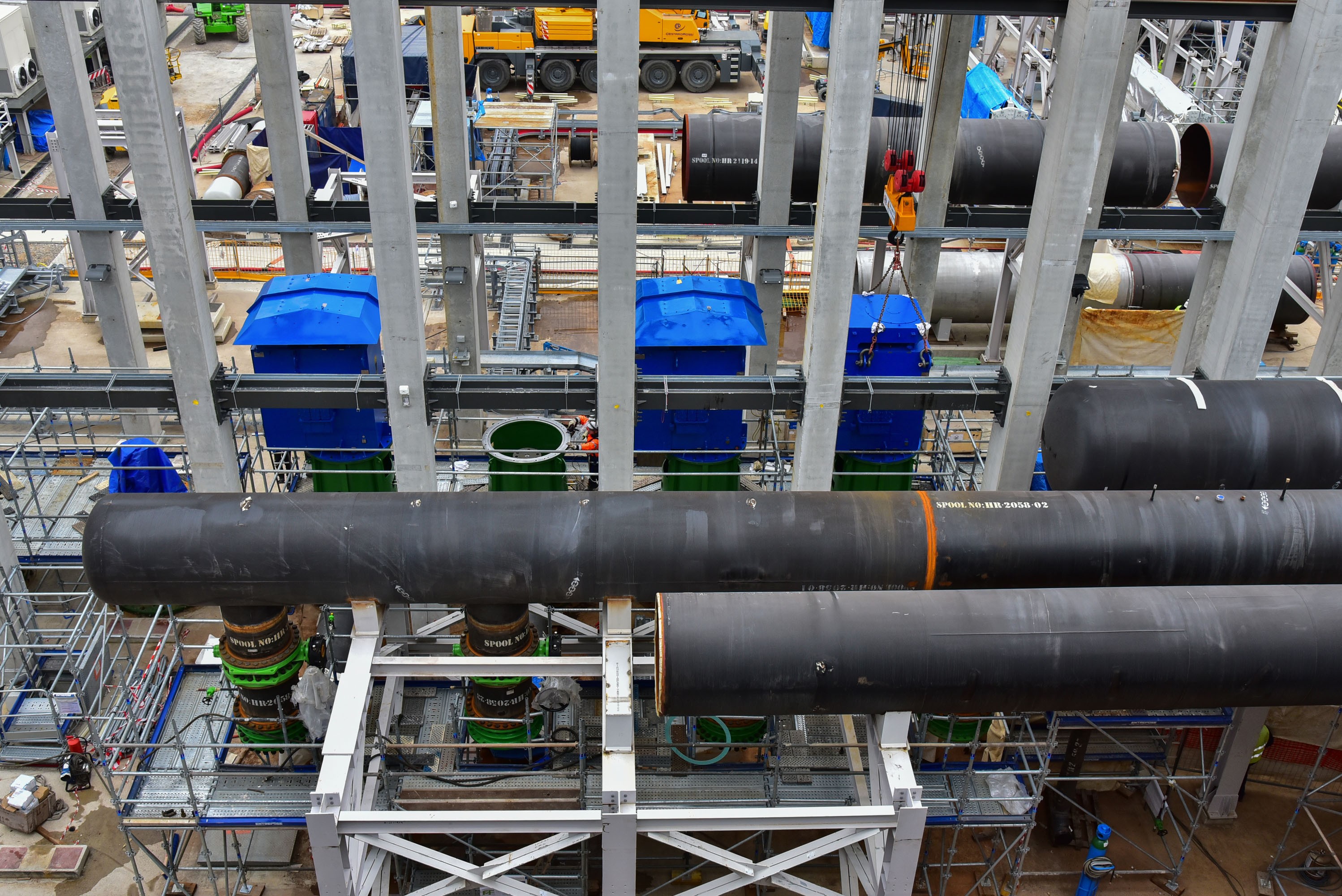
A set of 4,540 nozzles sprays the water coming in from the installation's cooling system over the stacked fill-pack layers. If unfolded, the total heat exchange surface provided by the fill pack would be approximately 704,000 square metres, the approximate equivalent of 70 soccer pitches.
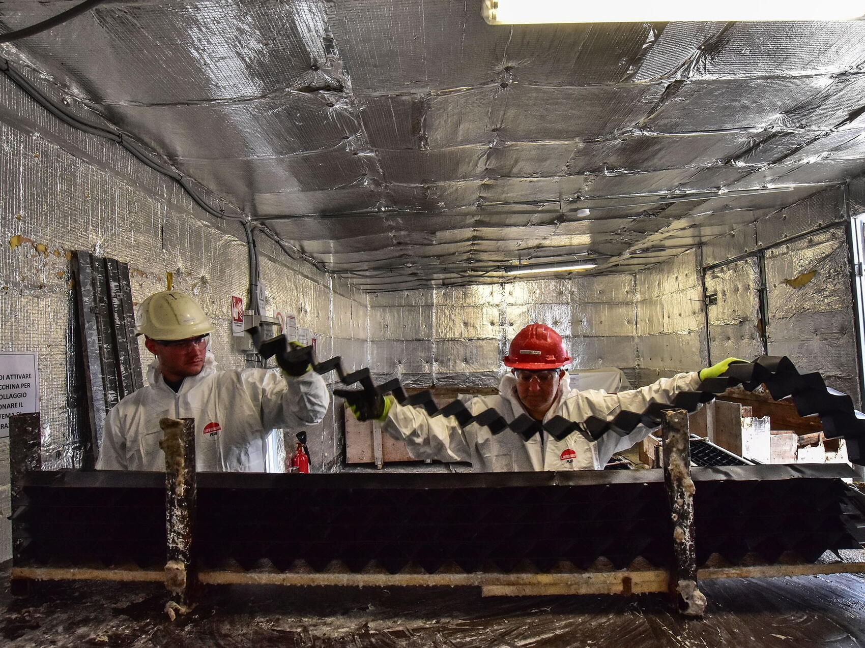
In order to recapture the water droplets that would be otherwise scattered by the upward draft, close to 4,500 "drift eliminator" packs located at the top of each cell provide a dense, zigzagging labyrinth that forces droplets to change direction, lose velocity and fall back into the cooling tower. Here, a worker is gluing millimetre-thick draft eliminator sheets into packs.