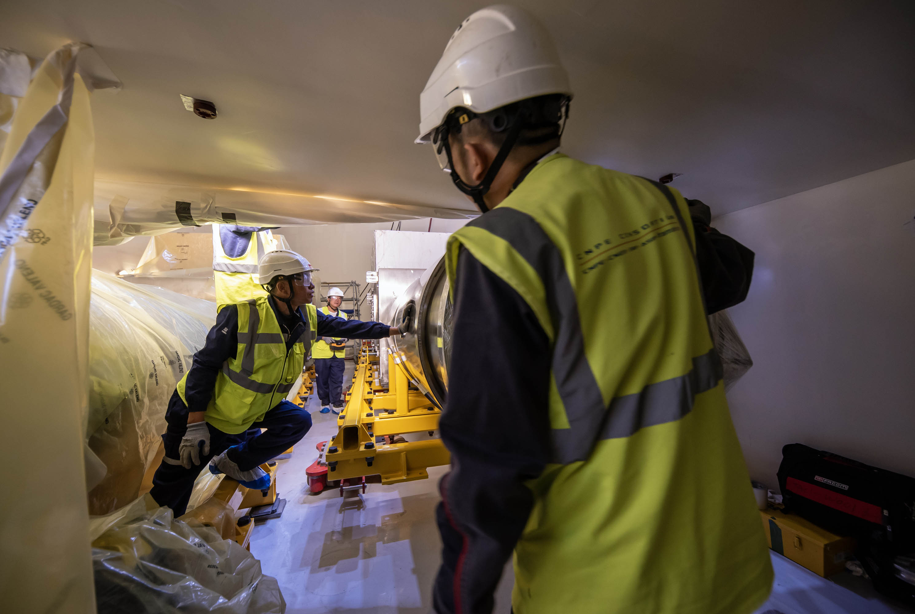
Feeders: the last gallery component takes its place
When referring to the 100 large pieces of equipment that must be installed in the Tokamak Building to create the magnet feeder network, the assembly team likes to make a distinction. “Gallery” components are the feeder segments that are installed outside of (and up to) the vacuum barrier of the machine—the cryostat. “In-cryostat” segments are on the opposite side of that same barrier, directly connected to the magnets. This month, a milestone was reached for the gallery components as the teams installed the 62nd and final element.
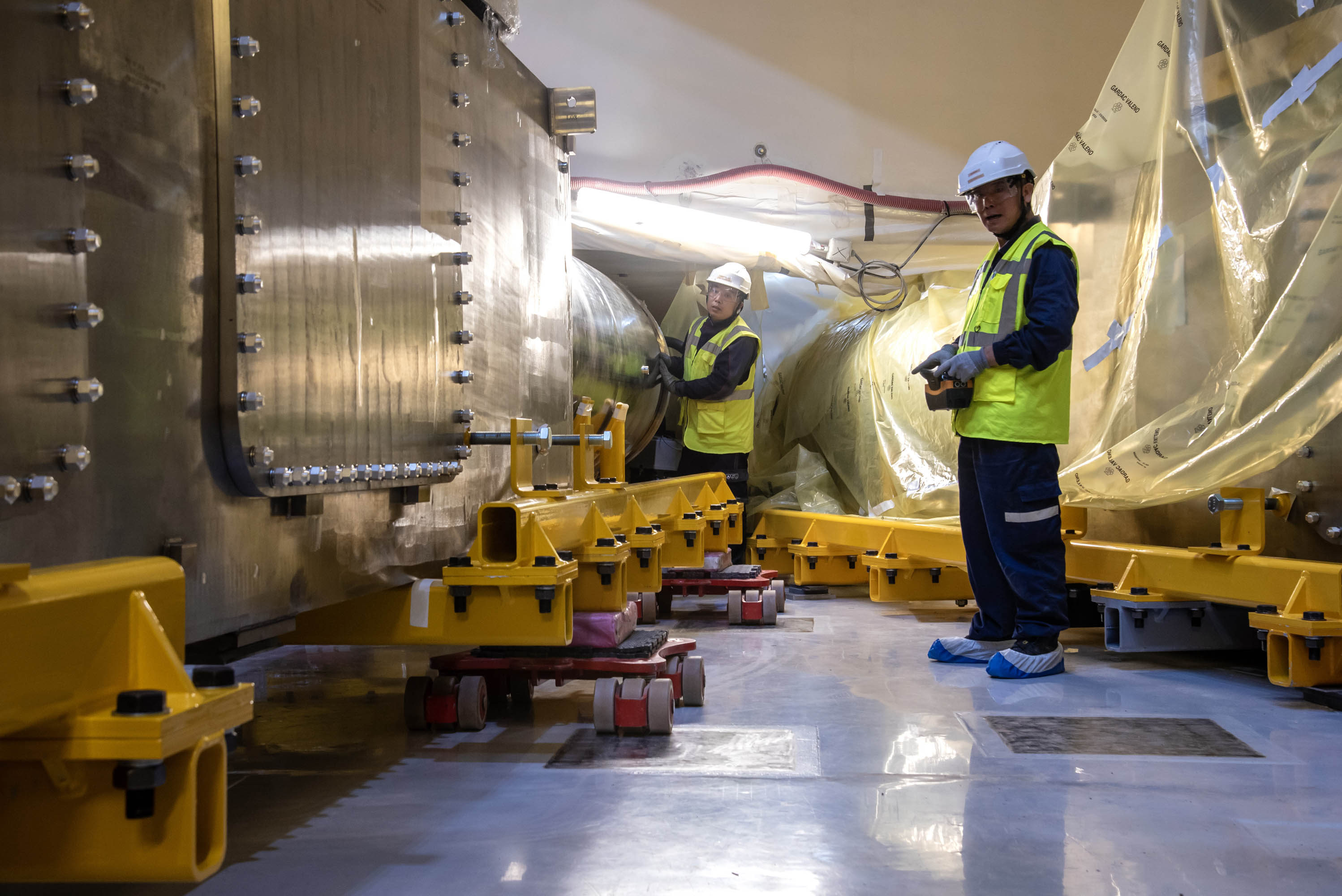
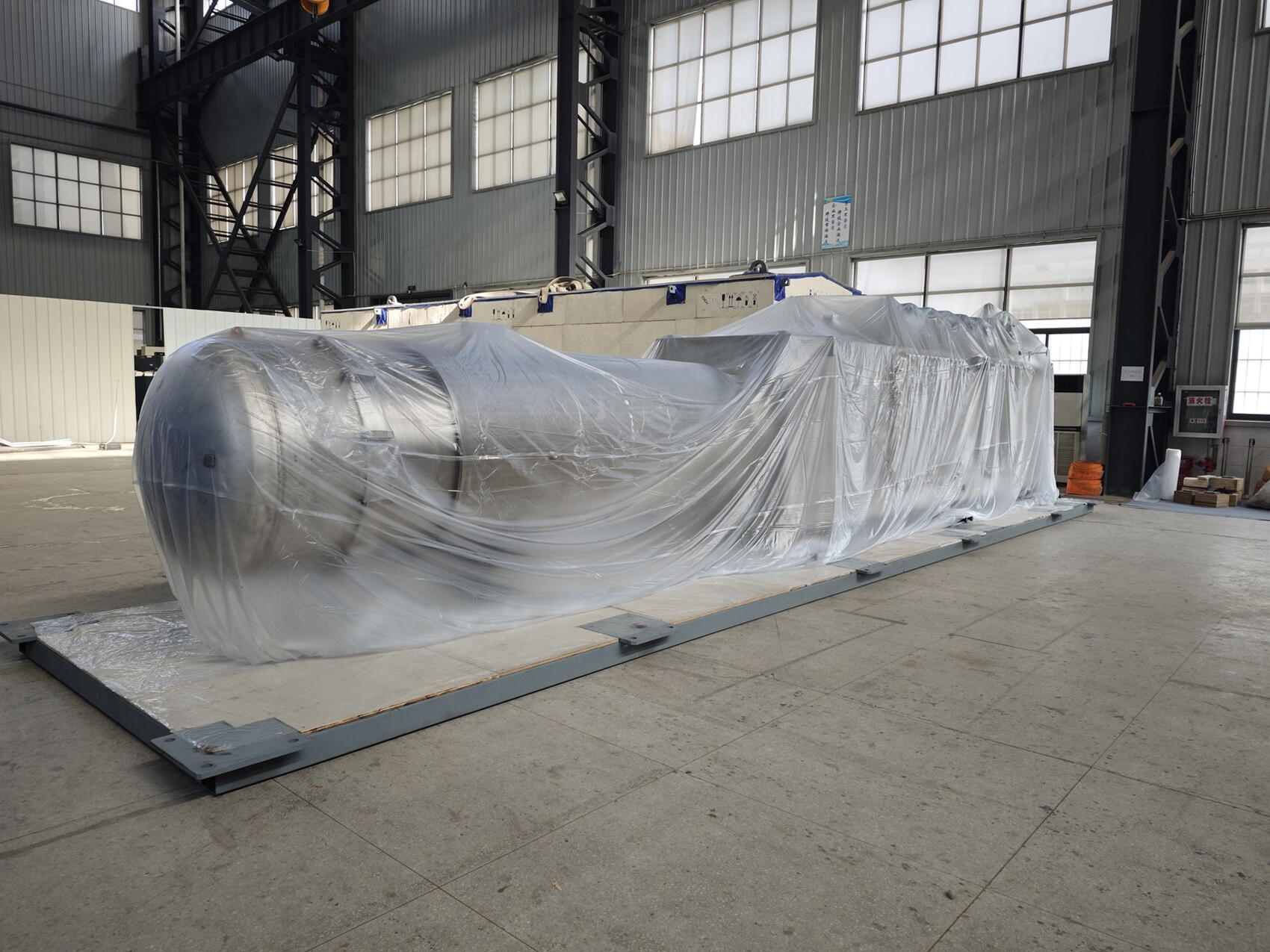
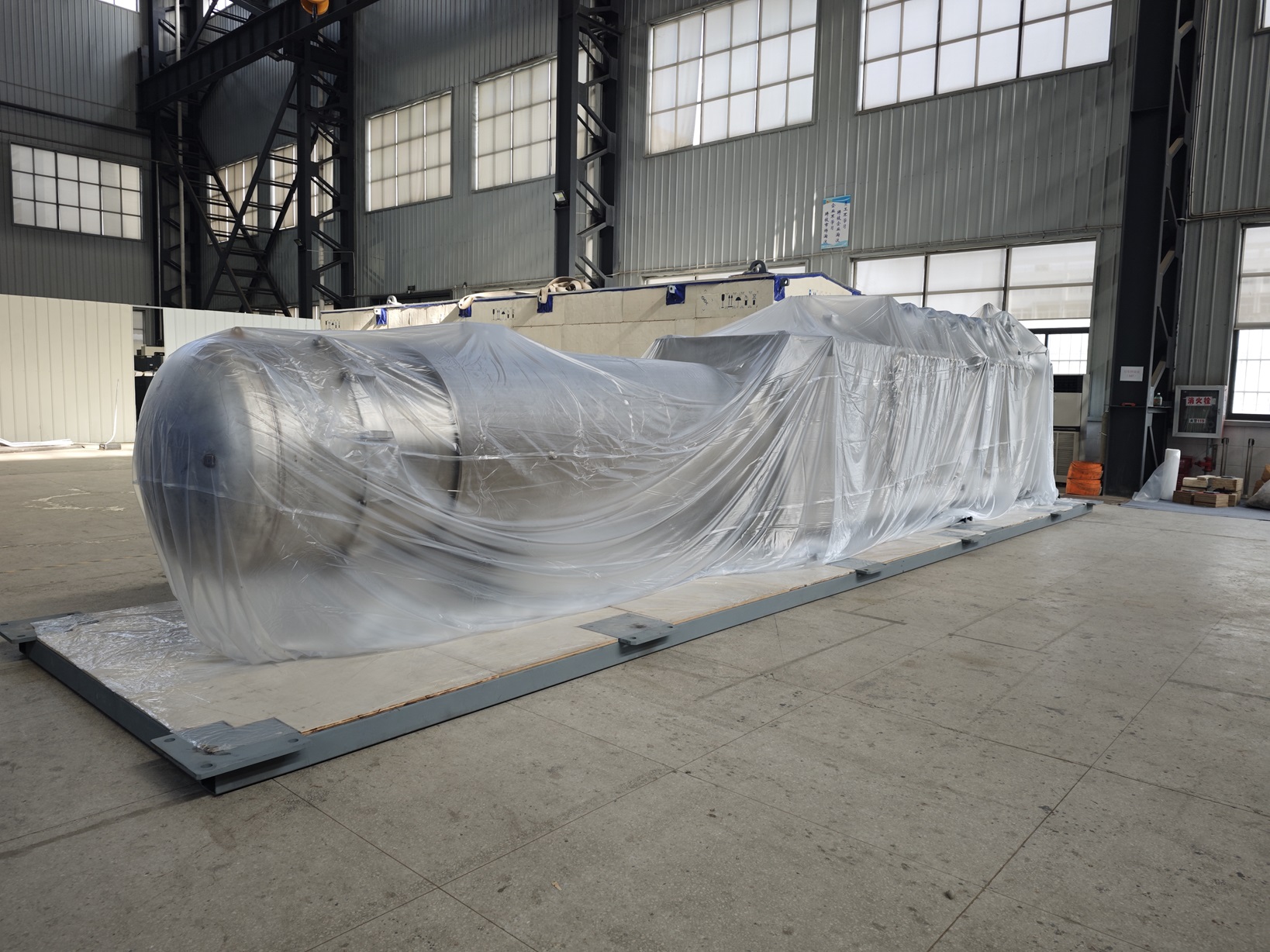
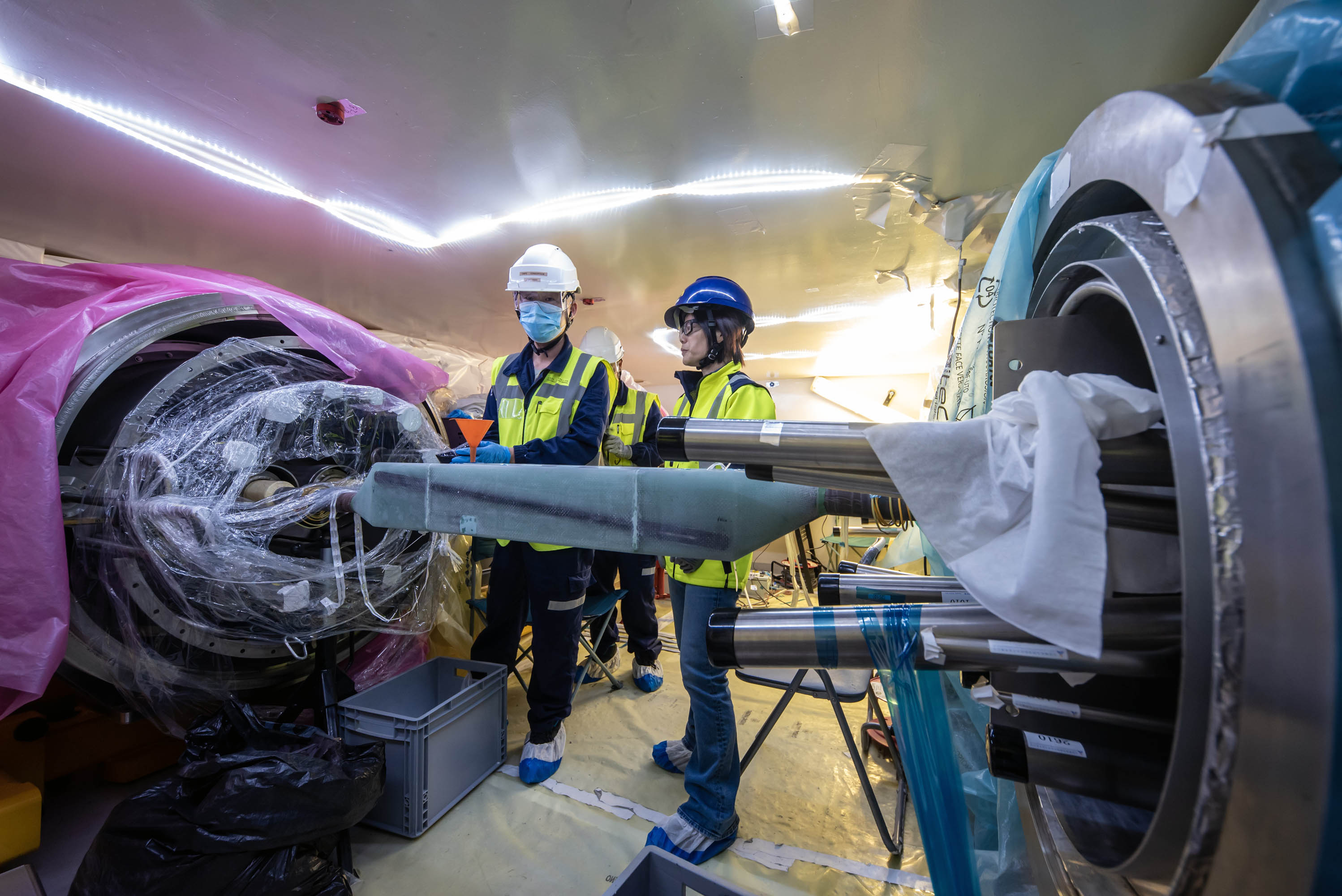
Feeders are the lifelines of the ITER magnet system, transporting everything they need to operate—cryogenic fluids, power, instrumentation—from the "warm" environment outside the machine in to the "cold" superconducting magnets operating at minus 270 °C. Under the procurement responsibility of ITER China, the feeders are manufactured in three fully instrumented segments and shipped to ITER for final assembly on site.
Built from nearly 100 large components—some 1,600 tonnes of equipment in all—the magnet feeder system is one of the major installation projects underway in the Tokamak Complex.

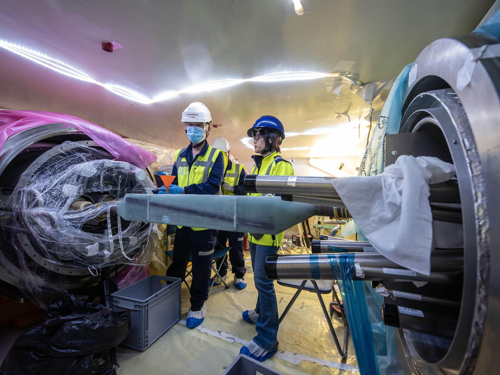
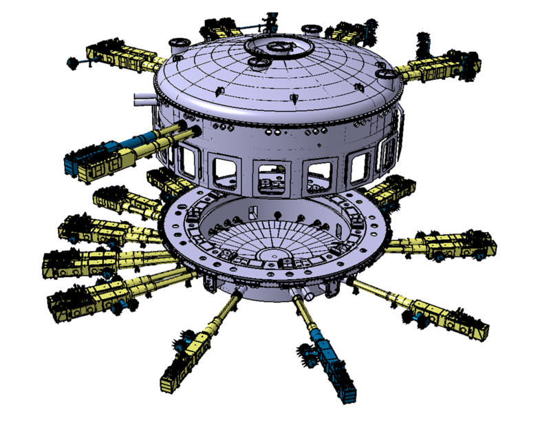
Magnet feeders evoke giant syringes that taper the closer they get to the magnets. Once fully assembled, these “thruways” can run as long as 40 metres in length. Thirty-one of these giant components will feed the toroidal, poloidal, central solenoid and correction magnet coils from their positions above or below the machine.
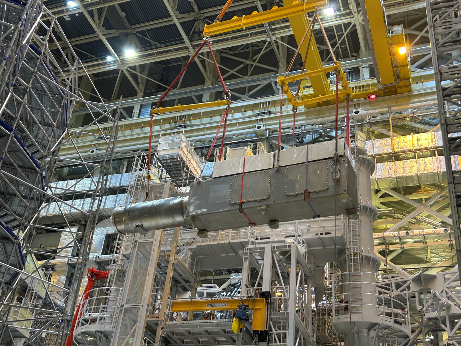
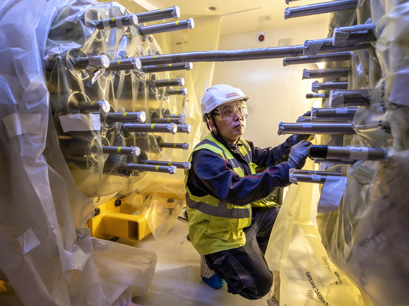
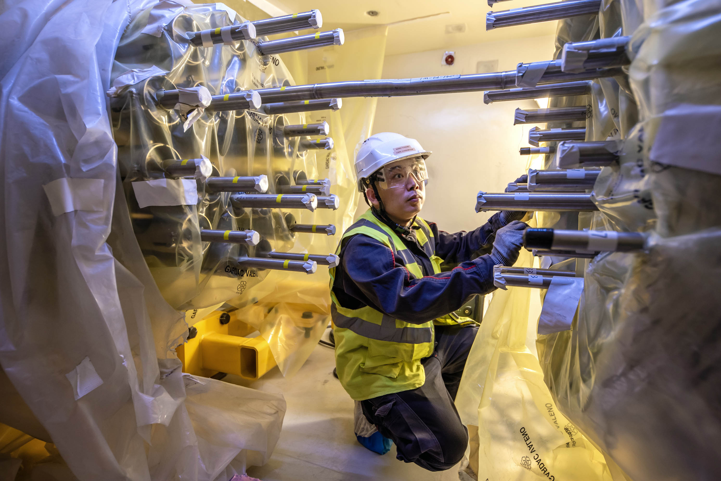
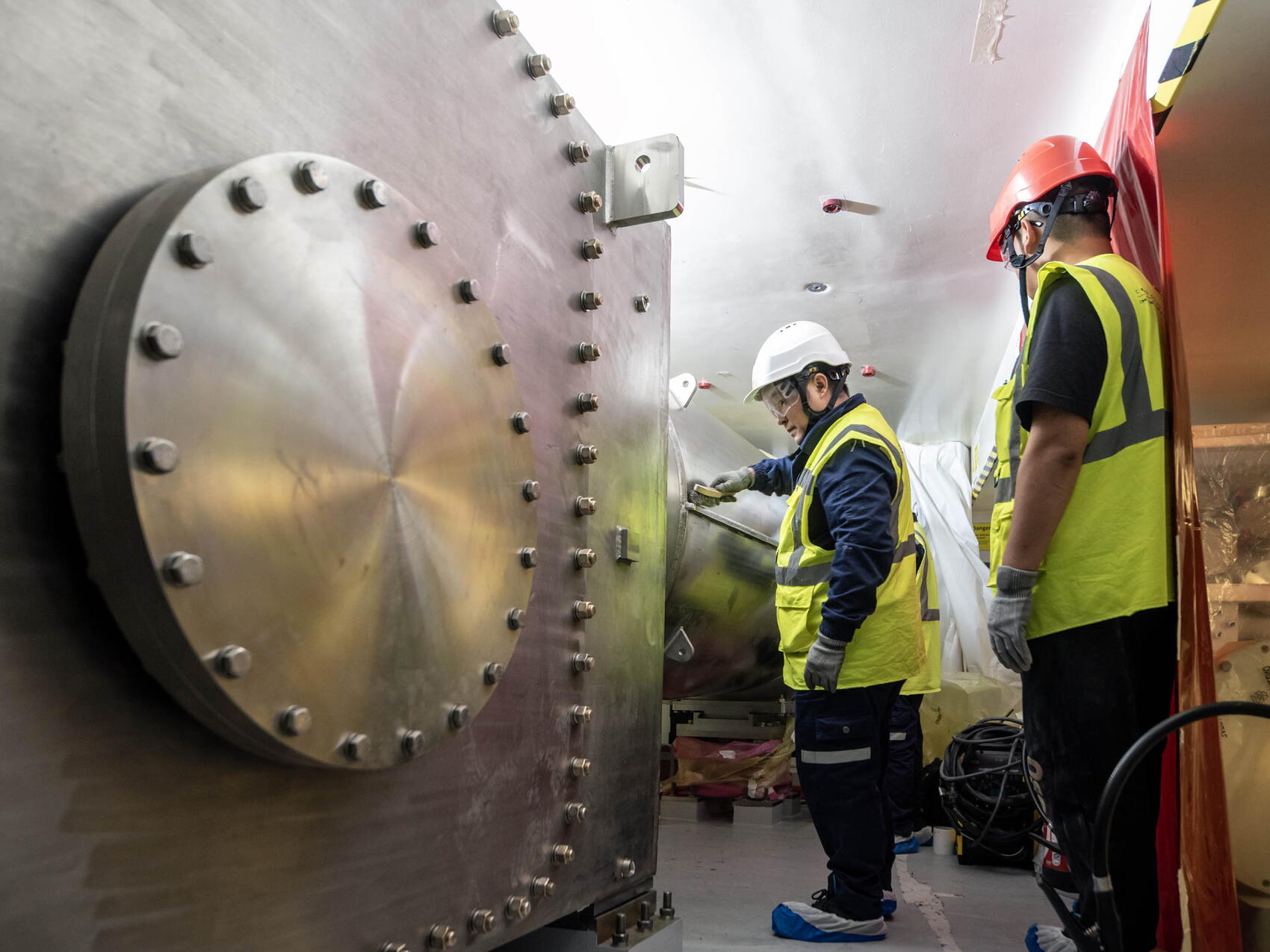
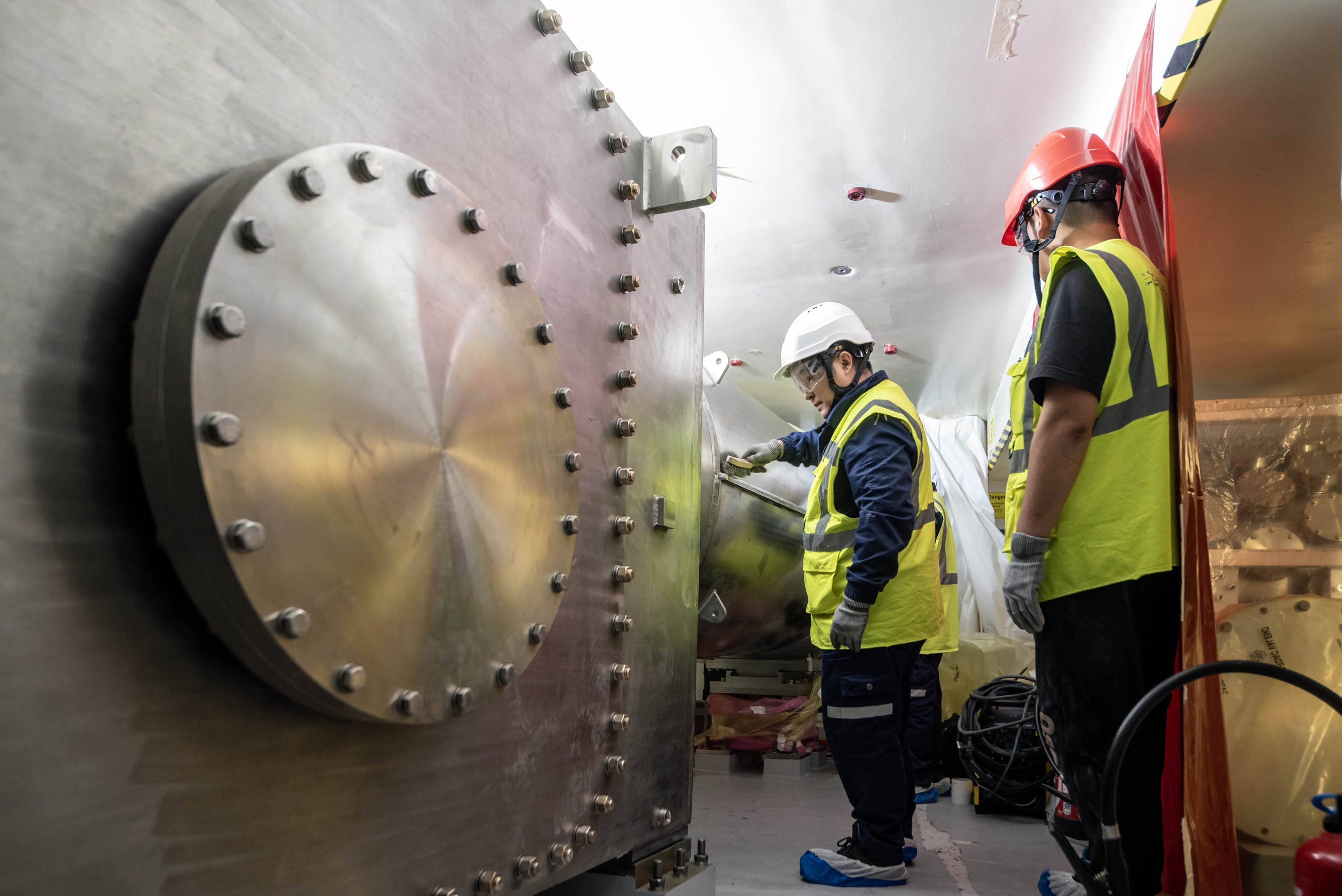
Two out of three of the segments required to build a magnet feeder are installed on supports outside of the ITER cryostat and are considered “gallery components” by the installation teams. These include the coil termination boxes—which are the furthest away from the machine, housing equipment that might require maintenance like cryo-valves, warm-to-cold electrical transition components, and sensors—and cryostat feedthroughs, which ferry the cryogens, the power, and the instrumentation through the concrete bioshield into the cryostat.
The final elements, in-cryostat feeders, adopt a variety of shapes inside the cryostat as they navigate the crowded environment to reach the magnet connectors.

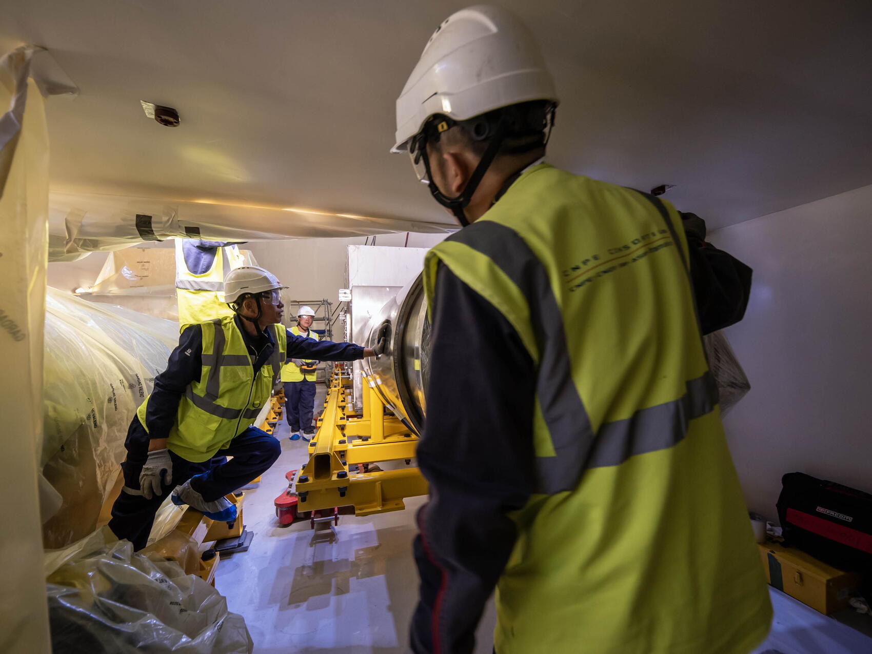
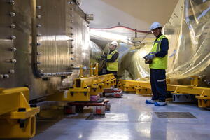
With the arrival of the last coil termination box on 19 September and its installation three days later, all 31* coil termination boxes and 31 cryostat feedthroughs have been delivered and installed, completing the gallery portion of the feeder system.
“From the start of manufacturing at ASIPP in China in 2015 to the delivery of the last gallery component this month, 10 years have passed,” says Man Su, technical responsible officer for the feeder system. “These were exciting years and this milestone is truly gratifying. I want to stress the collaborative nature of the work accomplished and recognize the important contributions of many at the Chinese Domestic Agency, ASIPP, and the ITER Organization—including workers, quality control and technical officers, and logistics teams."
*One coil termination box has been temporarily installed for use at the ITER magnet cold test facility, where several toroidal field coil magnets and one poloidal field coil will be tested before installation in the machine.
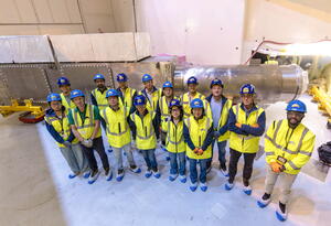
See the gallery below for more images of the feeder installation project.