Magnet protection system to step into the spotlight
Engineers will soon have the opportunity to test the protection architecture of ITER’s superconducting magnets in high-energy conditions.

A new experimental stage is taking shape at ITER—one that does not revolve around plasma, tritium, or even fusion power. Instead, it involves the protection architecture that will keep ITER’s massive superconducting magnets, and the investment they represent, safe from harm.
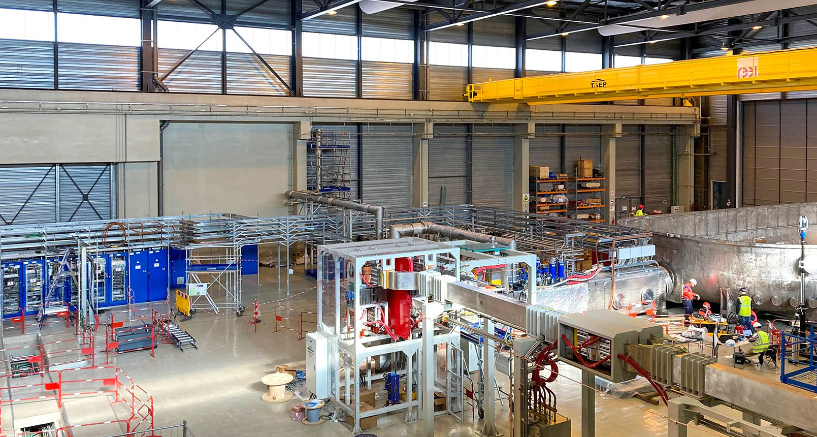
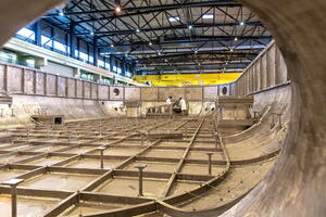
This work is centered at ITER’s magnet cold test facility where—in addition to testing some of the ITER toroidal field coils at 4 K (minus 269 °C)—engineers will have the opportunity to qualify protection systems before the magnets are permanently installed in the tokamak. Though the test setup will operate with only one coil at a time, it marks the first occasion where ITER’s magnet protection controllers—the fast and slow “brains” that detect, respond to, and prevent fault conditions—will operate under real, high-energy conditions.
“These magnets are captive components,” says Bertrand Bauvir, project leader of the Control Integration Project. “Once they’re installed on the sectors and the vacuum vessel and welded, it will take a tremendous amount of effort to replace them. So even if the risk of a manufacturing defect is very small, the potential impact would be catastrophic. The magnet cold test facility lets us verify that no systematic errors exist before we take irreversible steps.”
Testing the first fully integrated protection chain
The facility also serves a broader organizational purpose. “It is the first time ITER will go through integrated commissioning,” Bauvir says. “If we can’t succeed at this smaller scale, it means we’re not yet ready for the full machine. It’s a rehearsal—not just for technology, but for the people and processes that will make ITER work.”
The superconducting coils are among the most critical components in ITER. With almost zero resistance, they can carry enormous currents—up to 68 kA for the toroidal field coils with 41 GJ¹ of stored magnetic energy. If any part of a coil stops being superconducting, the sudden resistance generates intense heat, triggering what engineers call a quench.
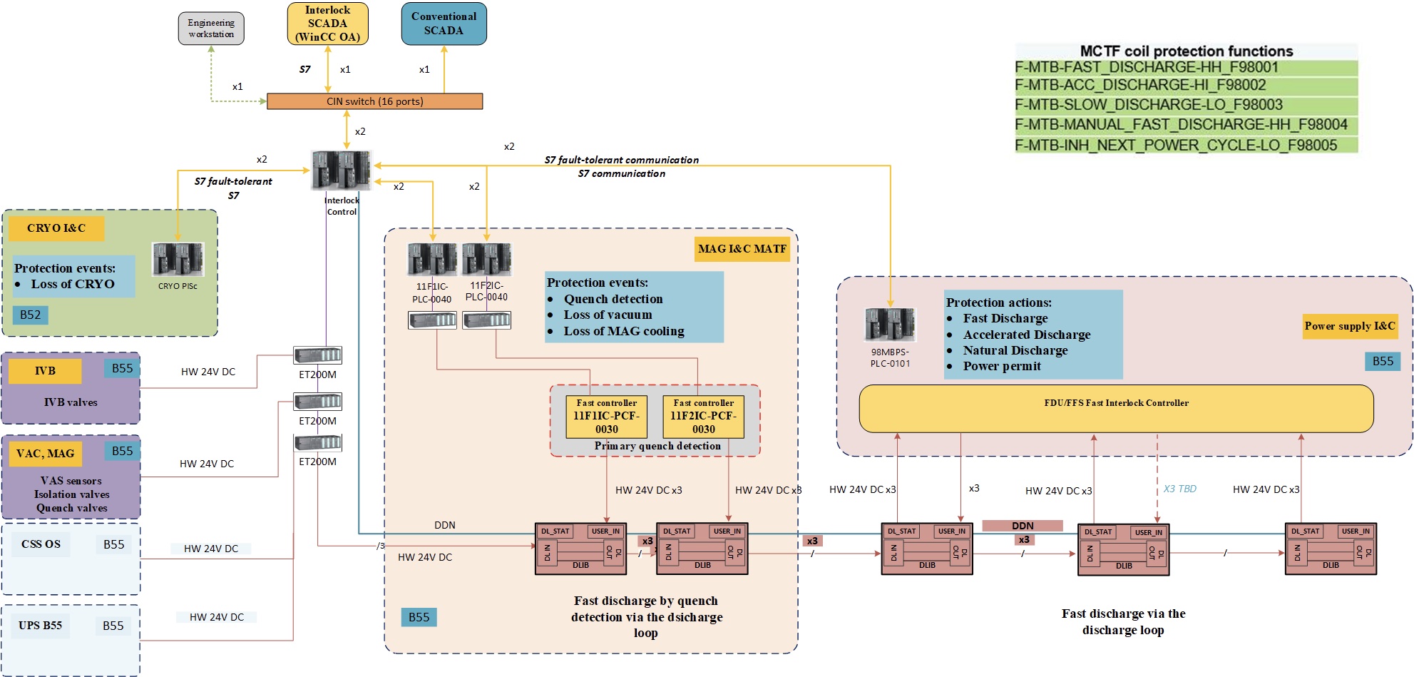
“The most important protection function in ITER is to detect a quench and safely remove the stored energy—and do it fast,” says Ruben Lopez, investment protection engineer and lead for the design of the magnet cold test facility protection strategy. “We have three complementary systems for that.”
• Primary quench detection is the fastest, using high-speed voltage measurements at coil and feeder taps. It samples at 1 kHz and must request discharge in less than 1.5 seconds.
• Secondary quench detection is slower, monitoring the thermo-hydraulic properties of the helium coolant. Quenches are detected by an abnormal increase in temperature, low helium flow or reverse helium flow.
• Safety quench detection is the slowest but independent third layer of protection for the toroidal field coils, based on differential pressure switch sensors that detect reverse helium flow.
If a quench occurs, coils must be discharged quickly by isolating them from their power converters and diverting the current into fast discharge resistors. “’Fast’ is no exaggeration,” Lopez says. “For the toroidal field coils, the current drops from 68 kA to about 5 kA in 30 seconds. That’s several gigawatts of power dissipated as heat in the resistors.” Because such rapid discharge puts stress on the coils, ITER’s protection strategy uses a defence-in-depth approach—discharging more gently (in a leisurely 30 to 120 minutes) when possible, but always fast enough to avoid damage.
Fast reflexes, deep protection
ITER’s protection architecture uses two types of controllers. Slow controllers, built on programmable logic controllers (PLCs), monitor thousands of signals related to helium flow, temperature, and pressure—conditions that evolve over seconds or minutes. Fast controllers, based on field programmable gate arrays (FPGAs), handle high-speed responses measured in microseconds. They detect events like an electrical arc or quench and trigger the appropriate action.
“PLCs are robust and can manage large, distributed systems,” says Bauvir. “But they can’t react in less than a millisecond. FPGAs can—they’re unbeatable for executing simple logic extremely fast.”
Reliability is critical. Many of the FPGA controllers operate in redundant pairs, performing the same computations independently and sometimes cross-checking results before acting. “This ensures the system doesn’t overreact because of a sensor glitch,” Bauvir explains. “We’re protecting not just against faults in the machine, but faults in the protection system itself.”

At the heart of ITER’s central interlock protection functions lies a hardware innovation called the discharge loop—a physical ring of FPGA-based electronic boxes known as discharge interface boxes. Each loop links all components involved in the magnet protection chain through a continuous current circuit.
“When the quench detection system opens the loop, every system sees it almost simultaneously,” Lopez explains. “That ensures the discharge is coordinated and immediate.”
Each loop originates in one of the Magnet Power Conversion buildings, interfaces with the Tokamak Complex housing the magnet systems, and ties together power converters, fast discharge resistors, and sensors. There are 21 discharge loops in total—one for the toroidal field system, five for the central solenoid, six for the poloidal field coils, and nine for the correction coils. The first two discharge interface cubicles were recently validated, marking a major milestone in the system’s rollout.
This dual approach—using both industrial PLCs and hardwired discharge loops—reflects ITER’s commitment to redundancy and speed. As Lopez notes, “The discharge loops are simple, physical, and extremely reliable. They’re the last line of defence to protect the coils.”
Each fast controller reports to a host controller, which Lopez likens to a “big brother.” While FPGAs handle real-time reactions, the host manages communications, firmware, and synchronization across the network.
“Everything must share the same notion of time,” says Bauvir. “When a fault occurs, we want to correlate events across the entire machine—whether it’s a quench, a change in the cryoplant, or something else. That requires microsecond-level time alignment.”
The magnet cold test facility is fully integrated with CODAC and the Central Interlock System, and uses the same high-performance network and data infrastructure as the main machine. “It’s essentially a mini-ITER,” Bauvir says. “Fewer components, but all the critical ones—the superconducting magnets, the cryoplant, the magnet feeder, the power supplies and the fast discharge units.”
Commissioning will unfold in two phases—first verifying that temperature, pressure, and vacuum sensors (“slow protections”) respond correctly and that basic interlocks function as expected, then in a second phase, testing quench detection systems using a superconducting short circuit nicknamed the “jumper.” If all goes well, the first tests with a real coil will begin in early 2026.
“This will be the first time we intentionally induce a controlled quench,” Bauvir says. “It’s our chance to prove that the entire protection chain—from sensors to fast discharge—behaves exactly as designed.”
For Lopez, the stakes could not be higher. “These magnets represent decades of work,” he says. “Once installed, it will be very hard to replace them. We need to make sure we can protect them as if they were newborns.”
¹ How large is 41GJ of energy? It’s the equivalent of 1) a 400-kilometre line of moving cars, one close to the other, travelling at 100km/h, or 2) the energy of the Statue of Liberty falling from a height of 20 kilometres.