you're currently reading the news digest published from 30 Nov 2015 to 07 Dec 2015
featured5
of-interest2
press6
featured
Preparing for the challenges of vacuum vessel welding
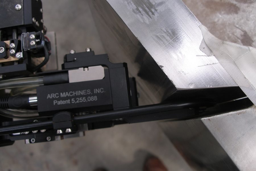
In 2012, the ITER Organization signed a EUR 74.5 million contract for the welding of the ITER vacuum vessel with the Spanish company Equipos Nucleares SA (ENSA). In addition to on-site welding and testing operations, the contract scope includes the development of specialized welding and testing tools and the qualification of processes and operators. In October 2015, an interim design review was the occasion to visit the ENSA facilities, where testing is underway on prototype welding tools. Welding operations for the vacuum vessel will be one of the longest and most complex sequences of ITER machine assembly, requiring around 200 personnel and at least four years to complete. The nine vacuum vessel sectors, supported by the overhead in-pit assembly tool, will be aligned and welded together at field joints first as pairs, then as triplets, and finally—in a quasi-simultaneous operation to ensure uniformity—the triplets will be joined to form the completed vessel. Fifty-three port structures, which provide openings to the vacuum chamber for maintenance, heating or diagnostics systems, must also be welded into place during the assembly of the vacuum vessel. If a pencil were to trace over the surface of all the vessel and port structure welds the resulting figure would measure 1.4 km, stretched end to end. But during vacuum vessel assembly the welding tools won't pass just once over each weld ... they'll pass an average of 35 times to build up thickness in 2 mm increments. This brings the total 'length' of deposited weld metal to 50 km, requiring at least 25 tonnes of welding wire. The welding tools will have to manoeuvre the complex geometry of the sectors and ports and reach areas that are not directly accessible to operators and where visibility is restricted. The robots will also be confined to welding from inside the vessel and ports, as the pre-installed vacuum vessel thermal shield makes access to the exterior surfaces impossible. 'One-sided welding is unusual and more challenging for welds of this thickness,' says Brian Macklin, an engineer in ITER's Tokamak Assembly Section. 'Customized equipment and techniques for welding, testing and examination are required. Weld shrinkage—which occurs naturally as weld material cools and solidifies—will have to be quantified and anticipated.' In 2012, the ITER Organization awarded the full scope of vacuum vessel welding operations—from the development of tools and qualification of processes and operators, through tool procurement and execution of welding operations at the ITER site—to the Spanish company Equipos Nucleares SA (ENSA). Today, engineering development and trials are underway at ENSA premises in Maliaño and Parbayón, near Santander, Spain, where a 12-person ENSA team is testing prototype welding tools on mockups that reproduce relevant segments of the vacuum vessel or ports. In one area, tests are underway on splice plate welding. The field joints between sectors or between sectors and ports require these transition pieces, which are custom machined to fit precisely. Welding robots will have to manoeuvre through the inner shell of the double-walled vacuum vessel to weld the splice plates of the outer shell, using narrow, custom-designed and custom-built welding torches. The tools are operated remotely, with cameras, screens and parameter monitoring to help the operators guide them through narrow gaps. At another station, a weld head is being trialled for the welding of a circular 'biscuit,' a solution that is being considered to allow the automation of the welding between splice plates. Other tests are underway to select the best filler material, to quantify shrinkage, and to demonstrate the tools on the complex geometries of the port structures, which will represent just over half of all welding work on the vessel. 'The vacuum vessel is a Protection Important Component, and it is absolutely critical that we perform high quality welds and that we can demonstrate this quality to the satisfaction of the authorities,' emphasizes Macklin. Detailed examination and leak-detection processes are under development to ensure the quality of welds. Visual examinations of the first weld pass (the root pass) by endoscopy is planned as the back side of the weld is not directly visible. The root pass and the final pass over each weld will also be leak-tested, an operation that will be repeated on the completed weld joint when a more precise test is possible. In addition, each weld will be subject to volumetric examination, required by the RCC-MR 2007 code* which applies to the vacuum vessel in order to confirm there are no defects in the weld. This examination is usually performed using radiography, but ultrasonic testing is also being developed for areas where radiography is not possible. The tools for these mandatory inspection tasks will have to work within severe space constraints, for example the clearance between the thermal shielding and the surface of the vacuum vessel which could be as low as 26 mm. At an interim design review, held late October at ENSA, Macklin and two colleagues from the ITER Organization were able to take stock of development work done to date. 'Before progressing to the pre-production phase of the contract, the ENSA team must demonstrate that they have fine-tuned all the welding parameters, finalized the tools, run the test sequences, and found the best ways of managing the weld shrinkage and distortion and of organizing the work to the required quality.' The panel was impressed with the work done so far by ENSA and concluded in its report that preparations for the production phase and the welding on-site of the sectors and ports are progressing well. The last step in the development phase of the contract is expected to take place late 2016, when the company plans to demonstrate sector-to-sector welding on full-scale 'slices' of the vacuum vessel sectors and full-size mockups of the ports. All of the welding and testing operations will be demonstrated and proven at this stage. 'This last step will prove the full set of processes and give us the confidence to proceed with the procurement of the tools for the production work on site.' * RCC-MR 2007 corresponds to the Design and Construction Rules for Mechanical Components of Nuclear Installations, 2007
Dressing the steel skeleton
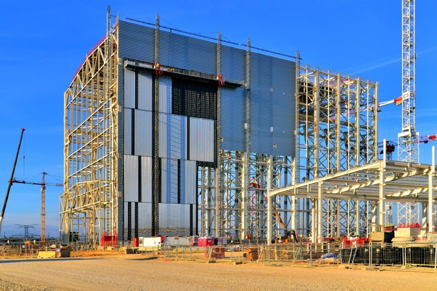
Watching the progression of cladding on the Assembly Hall building is like seeing an architect's drawing become reality. The mirror-like stainless steel surfaces already cover close to one-third of the east facade of the edifice and the impression is, as the architect intended, one of cleanliness and precision. The alternating surfaces of mirror-like stainless steel and grey-lacquered metal form the fourth and outermost layer of the 'skin' that will eventually cover the Assembly Hall: first, a first layer of steel cladding is bolted to the steel skeleton of the building, next comes 130-millimetre-thick rock wool insulation; and this layer in turn is covered by a polypropylene membrane in order to insure air tightness. Once these three layers are in place, the long (15 m) and narrow (1 m) mirror-like and grey-lacquered panes can be installed. All in all, some 14,000 m² of surface needs to be covered. When the work is done, we'll know if the building holds true to the architect's promise of reflecting the ever-changing shades of skylight and seasons.
Night shifts
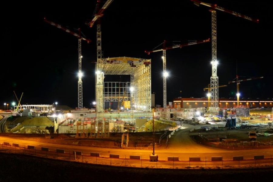
The ITER worksite hardly ever sleeps. When night falls and most employees leave the office to head home, another shift begins for construction workers and steel assembly specialists. This first panorama takes in most of the 42-hectare, one-kilometre-long ITER platform. To the left, between the concrete batching plant and the towering structure of the Assembly Hall, the steel-framed Site Services Building awaits cladding and roofing. This 80 metre-long facility will accommodate and distribute a large number of industrial support services and systems that are indispensable for operating the ITER installation. The 6:00 p.m. to 5:00 a.m. night shift is at work on the far side of the Assembly Hall, bolting together the steel lattice that will support the metal cladding. On the right side of the image, near the red-topped coil winding facility, a second team is busy installing steel reinforcement for the foundation of the ITER cryoplant. Let's zoom in now on the lower levels of the Tokamak Complex, where the evening crew is at work until 10:00 p.m. A square of light is visible in the background—we're looking into the Cryostat Workshop which is open late, exceptionally, in order for workers to prepare for a scheduled inspection of the building's gantry crane. This annual exercise consists of lifting a 220-tonne charge (10 percent heavier than the nominal lifting capacity of the crane).
Successful European collaboration on gyrotron prototype
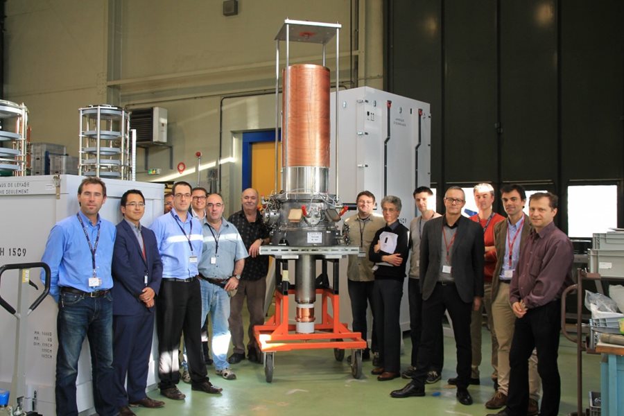
In ITER, powerful radio-frequency-generating devices called gyrotrons will generate microwave beams over a thousand times more powerful than a traditional microwave oven. These gyrotrons are part of the electron cyclotron heating system, one of the three systems that will heat the plasma in the ITER machine to 150 million degrees Celsius. In ITER, 24 gyrotrons will provide a total combined heating power of 24 MW. R&D work is progressing on gyrotrons in Europe, India, Japan and Russia as part of the development of the electron cyclotron system. Europe, responsible for the in-kind procurement of six gyrotrons, is working on the development of the final gyrotrons in collaboration with the European Gyrotron Consortium—made up of the European fusion laboratories KIT (Germany), the Swiss Plasma Center (Switzerland), HELLAS (Greece), and CNR (Italy), as well as the German USTUTT and Latvian ISSP as third parties—and Thales Electron Devices (France). Two industrial prototypes are currently in fabrication: a short-pulse gyrotron, capable of producing radio frequency of 1 MW for a few milliseconds; and a longer-pulse continuous-wave prototype, capable of producing a radiofrequency wave for several minutes. Following the pre-validation of the short-pulse gyrotron design in April 2015, the European Domestic Agency recently announced that the continuous-wave gyrotron prototype has successfully passed the final factory acceptance tests, in an important sign of progress for the program. The factory acceptance tests for the long-pulse continuous-wave gyrotron prototype, which will produce radiofrequency microwaves of 1MW of output power for a duration of several minutes, took place at the Thales facility near Paris. The tests comprised the checking of ultra-high vacuum level in order to guarantee long-pulse stable operation, the cooling circuits for dissipating the high heat fluxes of some internal components, and the high voltage withstand-off of the different gyrotron parts which are needed to accelerate the electrons at good efficiency. The completion of the factory acceptance tests is an important milestone, bringing the European agency closer to the critical phase of validation of the European gyrotron for ITER. Read the full story on the European Domestic Agency website.
Princeton lab invents a mirror mechanism for ITER
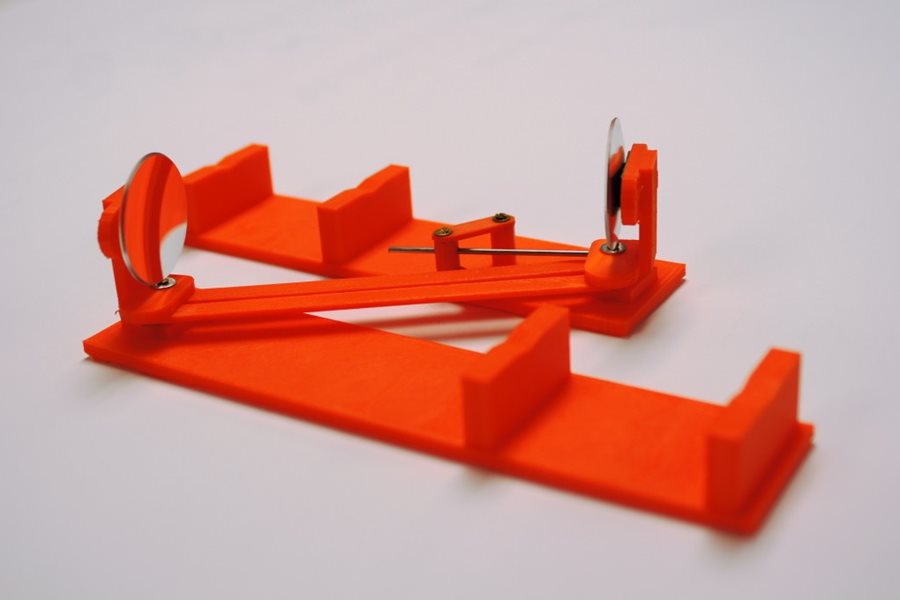
At the Princeton Plasma Physics Laboratory (PPPL) in the US, the spirit of tinkering lives. This past summer a team of engineers invented a mechanical device designed to be installed on ITER using 3D printing and parts bought at the supermarket chain Walmart. Known as a "self-aligning mirror mechanism," the invention consists of two horizontal bars, each with a mounted mirror, connected in such a way that no matter how the bars move the mirrors always stay in the same alignment with one another. Each bar is about a foot long and is made of orange resin, but the full-size version—what exists now is only a prototype—will have arms twice as long and made of metal. ITER will use the device to keep microwave beams that measure plasma qualities from being jolted off track when the temperature in ITER reaches 100 million °C, causing the metal structure containing the plasma to expand up to an inch. "We needed something to keep the beam in alignment," said PPPL engineer Michael Gomez, whom ITER tapped to design the device. Gomez teamed with PPPL engineer Ali Zolfaghari and Cara Bagley, a mechanical engineering student at Lehigh University (Pennsylvania, US). Bagley was at the Lab for the summer and performed functional analysis to make sure that the system that was developed would operate as designed. Gomez and Zolfaghari were initially contacted by Ben Tobias, a PPPL staff research physicist who is involved with ITER design. "We needed a way to automatically and precisely align a quasi-optical transmission line in a region of ITER with limited or no manned access," Tobias said. "One set of transmission lines is mounted on a large moving cart about the size of a mini-van, and those lines have to line up within about a millimeter of tolerance with a set of quartz windows leading to the plasma chamber." Tobias suggested a device without a motor that could adjust its orientation by itself. Electric motors could be damaged by either radiation or electromagnetic fields, and getting access for repairs would be difficult. Pneumatic motors, which are powered by compressed air, were ruled out because they would require specialized circuitry and increase the design's overall complexity. "My task was to find a simple solution that relied on mechanical principles," Gomez said. The resulting concept ensures that the diagnostic microwave beam will stay aligned if the ITER machinery expands or is jolted. Once they had finalized the design, PPPL engineer Bob Ellis used a 3D printer to create a prototype that would demonstrate the device. The printing technology allowed them to have a finished prototype in days. After the printed device had been completed, Gomez still had to find two mirrors. He found what he was looking for at Walmart—two concave mirrors that attached to the rear-view mirrors on a car to increase the driver's field of vision. When he dismantled the mirrors from their mounts, he found that the reverse side was also mirrored. And because this mirror was on the reverse, it had the concave shape he needed. "By luck I was able to find mirrors that were concave and the right size," said Gomez. Once the design had been more or less completed, Bagley used a computer program called "ANSYS Rigid Body Dynamics" to analyze how the device would actually move. "Bagley showed that the mechanism could adapt to any direction of thermal growth and movement of the vessel, including the radial, horizontal, and toroidal directions," said Zolfaghari. "In other words, she made sure that the mechanism would not jam or get overextended when used in different orientations." Gomez and Ali showed the prototype at PPPL's summer intern poster session in August along with Bagley. She found working on the system valuable, saying that "being given the chance to help bring a novel design from an idea to an invention disclosure was really rewarding for me." Princeton University has filed a provisional patent on the device. If private industry is interested in licensing the technology, the university plans to submit an application for a nonprovisional patent. The review process could take as long as several years. A full-sized metal prototype of the device will be built during the first quarter of 2016 and sent to General Atomics, a private company in San Diego that operates the DIII-D fusion reactor for the Department of Energy. The prototype will be tested under conditions that mimic those the finished device will encounter in ITER. A "paper review" of the device's design will be conducted by ITER staff in October 2017, and the finished version will be delivered to ITER in 2019. Read the original article at PPPL.
of-interest
WEST milestone: divertor coil casings installed
The aim of the WEST project is to turn the Tore Supra tokamak (France) into a test bed for ITER, with an actively cooled ITER-like tungstendivertor. Component installation is underway. The latest WEST Newsletter (#11) reports on the most recent milestone: the installation of the divertor coil casings. Two stainless steel rings constituting the housing for the conductor windings are now assembled and positioned inside the vacuum vessel at their nominal position. The building of the coil winding can now begin. (Photo Christophe Roux CEA-IRFM) Read all the latest from WEST in Newsletter 11 here.
RACE is on for ITER remote handling work
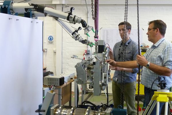
An 18-month development program to prototype remote handling tooling for the ITER fusion device was demonstrated on 26 and 27 October as part of collaboration between the European Domestic Agency for ITER and the Culham Centre for Fusion Energy (CCFE) in the UK. Representatives from the ITER Organization, the European agency, Assystem UK, and AMEC Foster Wheeler were at Culham to see a fully remote deployment of prototype remote pipe cutting and welding tooling developed by Culham's RACE (Remote Applications in Challenging Environments). Under a grant from the European Domestic Agency, RACE and CCFE's Engineering Implementation Department have produced a set of prototype tools intended for eventual use maintaining the neutral beam heating systems at ITER. Up to now, remote cutting and welding of process piping to the required codes, and under the challenging conditions of the ITER tokamak, had not been demonstrated, and is one of the higher risk areas across the ITER remote maintenance strategy. ITER will rely on remote handling for maintenance operations where space and/or environmental conditions in the machine do not allow manual intervention. Interconnected components, pipes, cranes and tooling will all need to be routinely repaired and maintained with millimetric accuracy. Read the full reports of the event on the European Domestic Agency and CCFE websites.