Captive components require a unique approach
Some parts of diagnostic systems need to be installed well before the systems are completely designed, creating a challenge in planning.

Some components of the ITER machine are referred to as "captive" because, once installed, they become boxed-in by other components or by a built structure and cannot easily be removed. Quite a few diagnostic systems have parts that fall into this category, including systems that have only just passed the conceptual or preliminary design review phase. Because these systems rely on rapidly evolving technology, it does not make sense to freeze their entire design years before the diagnostics will be used. But their "captive" elements must be completed and installed much earlier than the rest of the system.
Before installation contracts are awarded, ITER produces an "engineering work package," which is a set of instructions, guidelines and procedures that the contractor will use. Special considerations have to be made for the installation of these captive parts and components. Fortunately, the captive parts are generally not the most sophisticated elements of the systems—they are usually pipes or cables that convey signals back and forth from inside the plasma to the port plugs or places outside of the tokamak where diagnostic analysis takes place using more state-of-the art technology.
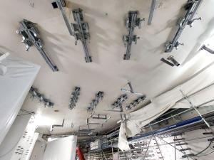
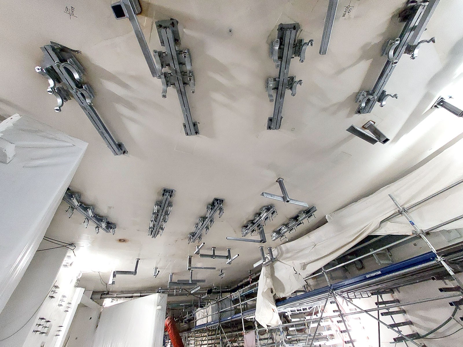
A good example of captive components is provided by the diagnostic systems that shine lasers and microwaves from outside the Tokamak Building all the way into the vacuum vessel. The beamlines are permanent metal structures, mostly consisting of pipes and supports attached to the gallery ceilings. As other systems are installed under the beamlines, the beamlines become captive.
Installation of captive components requires careful planning
"The construction team needs to pour concrete very soon to complete the walls around the tokamak," says Mark Kempenaars, optical diagnostics engineer in the In-Vessel Diagnostics Section, "They need to close holes in the walls, and it means that our paths will be frozen later this year. We will then lose access to these areas simply because other systems need to be installed all around them."
"Installing interfaces for diagnostics systems as captive components takes a great deal of planning," says Kempenaars. "We've produced hundreds of documents and drawings, and spent thousands of man hours for something that probably appears quite simple to someone on the outside."
Some of the pipes and supports go through the outer wall of the Tokamak Building—a 1.5 metre-thick, reinforced-concrete structure that acts as an outer container or "confinement barrier" for potentially contaminated air near the machine. Pipes and structures crossing this structure have to be carefully studied and installed exactly as specified to maintain high integrity confinement for the life of ITER.
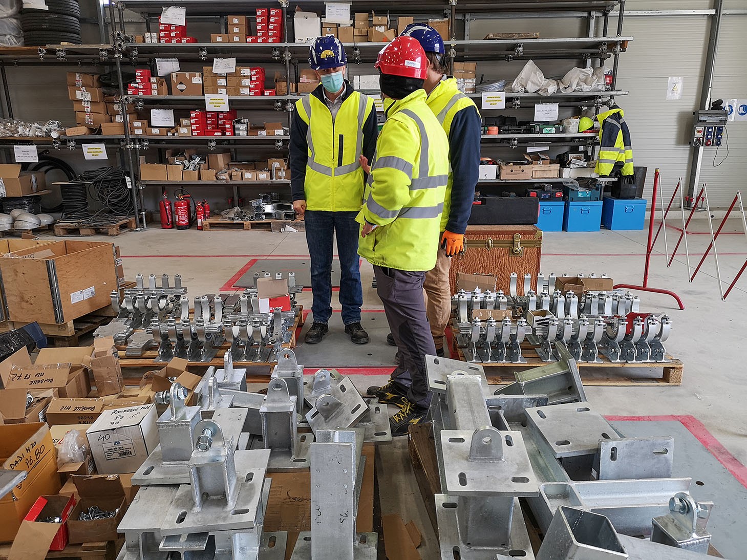
Components mostly arrive as kits. Every support is different but made from similar building elements. Imagine a set of LEGO models where every block is heavy, shiny and hard to identify, except by reading the unique part numbers marked on it and matching them to incredibly detailed drawings. The assembly of these metre-long kits to millimetre precision before they are attached to the building is exacting work and must be executed flawlessly to allow these heavy components to fit in the building correctly and on the first attempt.
The first captive systems serve as a model for the rest
Installing captive elements of the diagnostics systems has required a change of mindset. Developers have had to stop following a traditional approach of design, implementation and installation. They now embrace a parallel model, where captive parts of the system are frozen while other parts are still in design. They plan for the parts to arrive within the construction timeline, with built-in margins to avoid cascading delays.
Kempenaars is the technical responsible officer for two diagnostic systems, which being at the lowest of the diagnostic levels, serving the divertor region of the plasma, were the first to be affected by the construction tidal wave. To add to complexity, they are in a corner area of the Tokamak Building where there is a lot of interaction with other systems. These systems are among the trickiest to fit, as they have to dodge cable trays and cryogenic lines.
"Because my systems are the first to be installed, I was the first to have to raise engineering work packages, to get them into the system, to get them approved, to get them manufactured and get the ball rolling," says Kempenaars. "This is how I ended up setting the example."
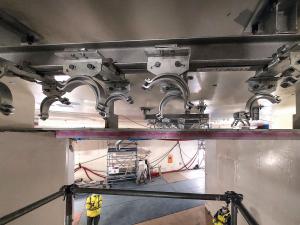
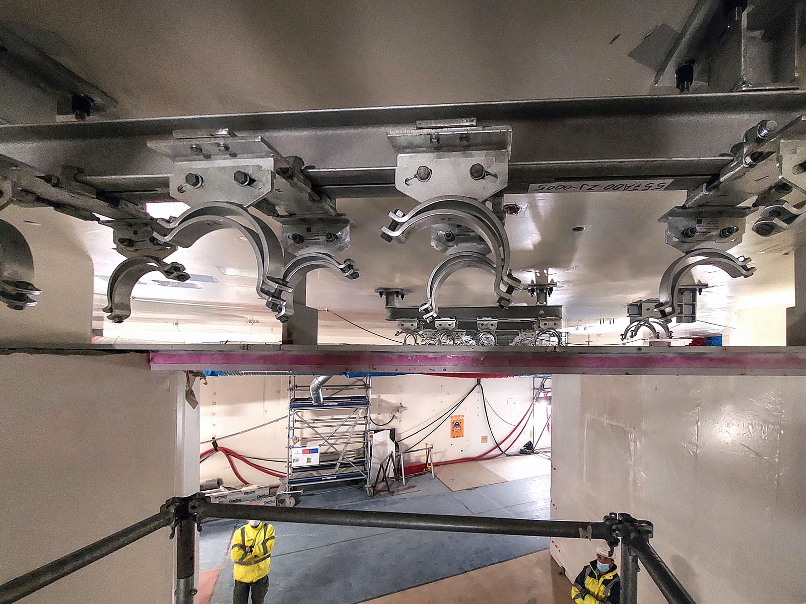
"Now, roughly two-and-a-half years later, we're at the stage where the installation contractor is starting to install system elements into the building and to bolt hardware onto the ceiling for us. Knowing all the work that it took to arrive at this stage, there is incredible satisfaction in the team as they see these steps being taken. It shows that all our planning and coordination have been successful, and serves as a model for subsequent systems."