Lettres d'information

Choisissez ce que vous souhaitez recevoir :

Merci de renseigner votre adresse de messagerie électronique :

@

Votre adresse email ne sera utilisée que dans le cadre de campagnes d'information ITER Organization auxquelles vous êtes abonné. ITER Organization ne communiquera jamais votre adresse email et autres informations personnelles à quiconque ou dans le cadre d'informations commerciales.

Si vous changez d'avis, il vous est possible de vous désinscrire en cliquant sur le lien 'unsubscribe' visible dans vos emails provenant d'ITER Organization.

Pour plus d'information, veuillez consulter notre Politique de confidentialité.

Actu & Médias

Links

Of Interest

See archived articles

Conferences


In ITER, the devices that need to be attached to the walls (or floors, or ceilings) can weigh several tonnes. Embedded plates are the solution for extremely robust anchorage.
Attaching a coat rack or shelf to a wall in your home is a relatively easy operation: drill a couple of holes, insert a dowel or wall plug, add the proper screws and the job is done.

In ITER, of course, things are slightly more complex. For structural as well as for nuclear confinement reasons, drilling holes in the walls of the installation is not practicable. And the devices that need to be attached to the walls (or floors, or ceilings)—the equivalent of our shelves and coat racks—can weigh several tons.

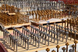
The solution comes in the form of an embedded plate. If you look at an embedded plate before it is embedded you might mistake it for a small coffee table equipped with supernumerary legs. Although embedded plates come in different sizes, they all consist of a thick steel plate onto which are welded equally thick steel studs with rounded heads.

Embedded plates are inserted into the rebar lattice prior to pouring concrete. As the plate is positioned in accordance with the 3D Configuration Management Model and tuned with a precision instrument (theodolite) in order to be level with the future concrete surface, the studs (up to 16 for the largest plates) penetrate deep into the lattice.

Once the concrete is poured and has set, the studs and their rounded head provide extremely robust anchorage, capable of supporting loads of up to ~90 metric tons in pure traction.

Equipment supports such as magnet feeders, cooling water system tanks, diagnostic systems, cryolines, cable trays, etc., can then be welded onto the plates.

In the floors, walls and ceilings of the Tokamak Complex there will be roughly 60,000 such embedded plates—16,000 in the basemat slab alone. Another significant client: the cable trays running inside the Complex and throughout the galleries outside will require 20,000 plates.

Although Configuration Management Models are very precise tools for positioning the plates, calculations and models must be confronted to reality. This is one of the roles played by the B2 slab mockup, a 150-square-metre structure that reproduces the complex rebar arrangements of the Tokamak Complex basemat slab.

"As with the rebar and concrete, we need to have hands-on experience of the difficulties we might encounter in the installation of the embedded plates," explains ITER Nuclear Buildings Section Leader Laurent Patisson.

The density of plates is such that there will almost certainly be some instances of conflict between the rebar lattice and the planned positioning of the plates. "The Configuration Management Model is now frozen for the B2 slab and will soon be frozen for the other levels," says Laurent. "If and when we encounter this type of conflict, the systems will have to adapt."


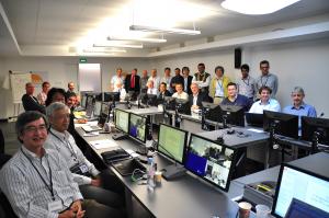
Leading plasma scientists, plus key engineers and scientists from the ITER Organization, met at Headquarters last week to reassess the ITER Research Plan.
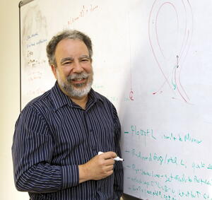
Last week, 21 of the world-leading plasma scientists plus key engineers and scientists from the ITER Organization came together at the ITER Headquarters for two days to reassess the ITER Research Plan.

Since its implementation as one of the ITER Baseline documents in 2010, the boundary conditions for the installation of certain components have changed. Accordingly, an update was necessary to the Research Plan that defines and coordinates the project's research activities on the path towards deuterium-tritium fusion power.

The ITER Research Plan is one of the major ITER Baseline documents. It describes the principal physics research activities to be carried out during ITER construction, together with an initial definition of the experimental program planned for the first ten years of ITER operation leading to the production of several hundred MW of fusion power.

However, since the schedule for the installation of some of the critical components has changed, the physics community sees itself confronted with some essential uncertainties. "For example, cost pressures have necessitated a rescheduling of the installation date of some of the key ITER measurement systems and elements of the heating and current drive systems," says David Campbell, Head of ITER's Plasma Operation Directorate. "It is therefore up to us to define the requirements from the physics side to ensure that we can achieve ITER's ambitious scientific goals within the foreseen timeframe."

The conclusions of the workshop on the ITER Research Plan, including recommendations on installation sequencing for some key plasma heating and measurement systems, will be presented to the ITER Science and Technology Advisory Committee (STAC) which will convene at ITER Headquarters on 14-16 October.

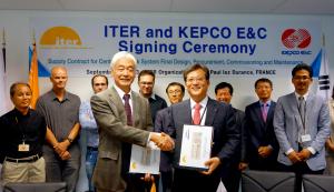
Signing the contract for the final design and procurement of the Central Interlock System: ITER Director-General Motojima and KEPCO E&C's Soon-Chul Yun, executive senior vice president of the Nuclear Division.
On Wednesday 25 September, the ITER Organization signed two contracts with the Korean firm KEPCO E&C in back-to-back ceremonies that took place on the fifth floor of the ITER Headquarters.

The first contract covers the final design and procurement of the Central Interlock System, the ITER control system dedicated to machine protection. Together with CODAC and the Central Safety System, Central Interlock is the third of the three ITER Instrumentation and Control (I&C) central systems in charge of the correct and safe operation of the Tokamak.
 
A huge number of physical and functional interfaces will exist between the local control systems integrated into every component or plant and the three I&C systems. For Central Interlock, the R&D and prototyping phase was brought to a close last year with the successful preliminary design review that took place in December. KEPCO E&C and its consortium partners will now take over the detailed engineering design, procurement (hardware and software) and commissioning of the Central Interlock System up to First Plasma.

The participation of the National Fusion Research Institute (NFRI) in the KEPCO E&C consortium means that the ITER system will be tested in situ at the KSTAR Tokamak in Korea—a significant advantage for the evaluation and validation of the selected technologies.

The second document signed by ITER Director-General Osamu Motojima and Soon-Chul Yun, executive senior vice president of KEPCO E&C's Nuclear Division, was the Second Work Plan for Cable Engineering Support Services, which will run until May 2017.

This engineering framework contract signed in May 2012 provides engineering support for the design and routing of over 10,000 kilometres of cables throughout the ITER installation, the design of 200 km of cable trays and their seismic supports, and the production of cable tray manufacturing drawings and cable installation reports.

This Second Work Plan starts on 1 October 2013 and covers the build-to-print drawings for Tokamak Complex cable trays, including supports and most of the cable routing cards for the First Plasma. One KEPCO officer is permanently based out of ITER Headquarters to liaise between the ITER Electrical Engineering Division and the KEPCO team back in Seoul.