Lettres d'information

Choisissez ce que vous souhaitez recevoir :

Merci de renseigner votre adresse de messagerie électronique :

@

Votre adresse email ne sera utilisée que dans le cadre de campagnes d'information ITER Organization auxquelles vous êtes abonné. ITER Organization ne communiquera jamais votre adresse email et autres informations personnelles à quiconque ou dans le cadre d'informations commerciales.

Si vous changez d'avis, il vous est possible de vous désinscrire en cliquant sur le lien 'unsubscribe' visible dans vos emails provenant d'ITER Organization.

Pour plus d'information, veuillez consulter notre Politique de confidentialité.

Actu & Médias


Pour les actualités en français, voir la page Actus & Médias.

Twisting and turning

Men at work: Songtao Wu, Jens Reich, Fabien Ferlay, Jo Preble, Mark Norman, Jack Sky, Edward Daly and Brian Macklin from the various ITER divisions discussing the best way to assemble the vertical stability coils. (Click to view larger version...)
Men at work: Songtao Wu, Jens Reich, Fabien Ferlay, Jo Preble, Mark Norman, Jack Sky, Edward Daly and Brian Macklin from the various ITER divisions discussing the best way to assemble the vertical stability coils.
As part of ITER's in-vessel coil system, two vertical stability (VS) coils will provide fast control of the vertical displacement of the plasma. The circular VS coil situated in the lower segment of the vacuum vessel is the larger of the two, with a radius of 7.6 metres and a weight of 2 metric tons. The upper VS coil has a radius of 5.8 metres and weighs 1.6 metric tons.

The conductor inside of these coils—the largest of its kind ever—consists of a stainless steel jacket, magnesium oxide insulation, copper alloy to conduct current, and a water-cooling channel in the centre (also see Newsline 175 and 151).

While over the past months many discussions have taken place regarding the design of the VS coils, assembly engineers within the ITER Organization are facing a difficult challenge of their own: how to bring the bulky coil segments in through the port openings of the sealed vacuum vessel.

"We want to try to install the largest coil segments possible into the vacuum vessel to reduce the number of brazed joints to be performed on the inside of the vessel, reducing cost and schedule but more importantly increasing the reliability of the coils," explains Mechanical Engineer Brian Macklin. "The installation of the VS coils is one of the first activities to be performed after the welding of the vacuum vessel sectors. The target is to install three 120° segments. Alternatives include four 90° segments or pre-installation of the segments in the vacuum vessel sectors." However, pre-installation of the VS coils before the sector assembly is not the preferred option, because the coils would compromise the welding of the vacuum vessel. In addition, there is a risk of damaging the coil segments.

The current plan for the installation of the VS coils involves guiding 120-degree coil segments through the equatorial ports into the vacuum vessel. Once inside the vacuum vessel, the segments are to be assembled in a series of steps that include alignment, brazing, welding, non-destructive examination, vacuum-leak checking, pressure testing and electrical testing.

It's already spectacular as an illustration, but wait until you've seen it moving in 3D: one 120-degree coil segment on its guide rails. (Click to view larger version...)
It's already spectacular as an illustration, but wait until you've seen it moving in 3D: one 120-degree coil segment on its guide rails.
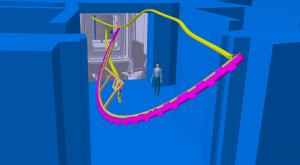
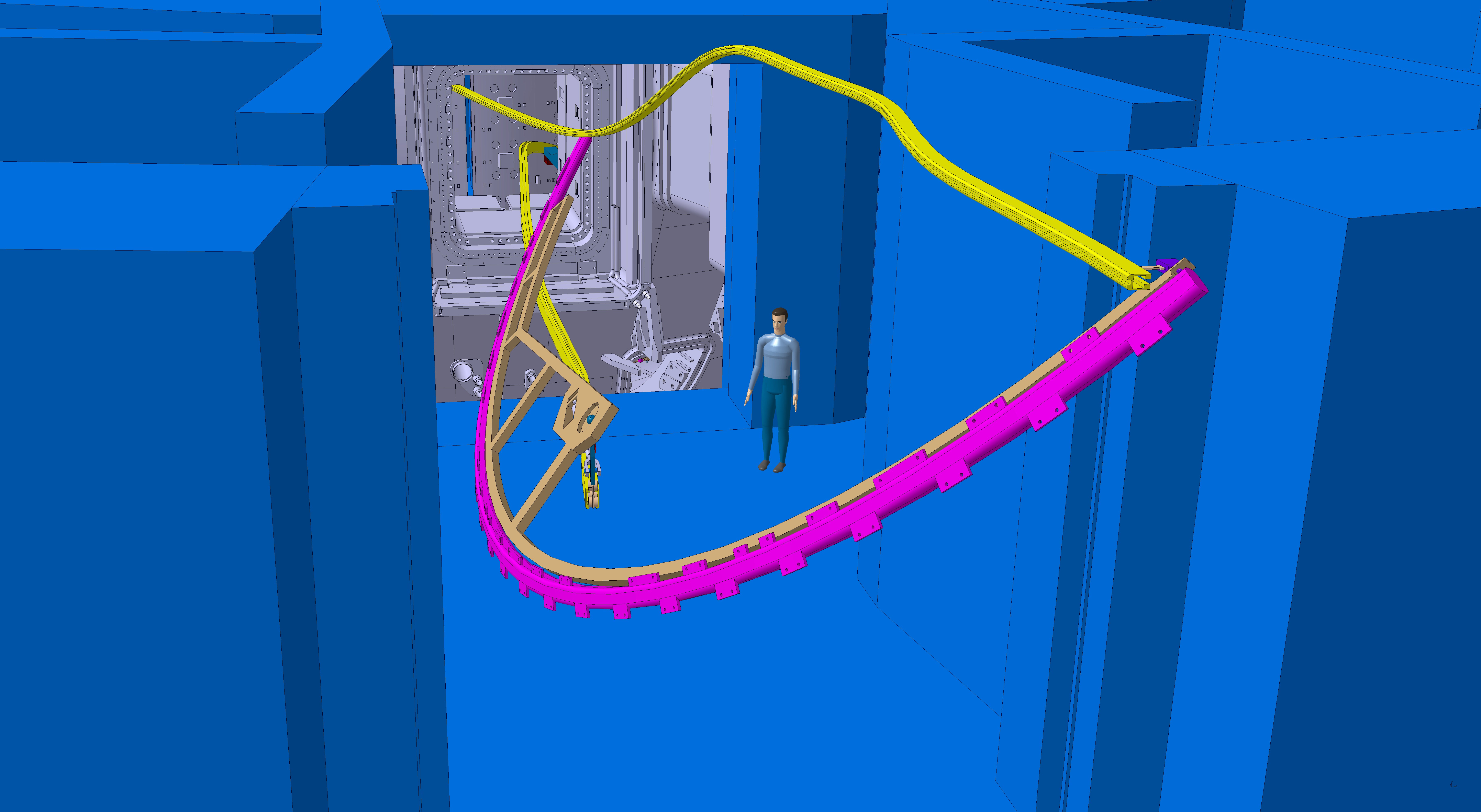
Easing the bulky coils into the vacuum vessel through small openings will be no easy task. Specially designed rails and handling fixtures will have to be installed to guide the bulky coils on their roller coaster ride through the port cell and the vacuum vessel port to their final destination. "I would liken the job to moving a couch into a new apartment—twisting, turning and rotating it as you climb up three flights of stairs and through several narrow hallways and a few really narrow doorways," says ITER mechanical engineer Ed Daly.

The challenge is now solved on paper: the drawings and models are finished and the objective of introducing the three segments seems feasible. But when dealing with the mechanics of assembling the world's largest fusion device you'd better double check your calculations.

Specially designed rails and handling fixtures will be mounted to guide the coils on a roller coaster ride through the port plug. (Click to view larger version...)
Specially designed rails and handling fixtures will be mounted to guide the coils on a roller coaster ride through the port plug.
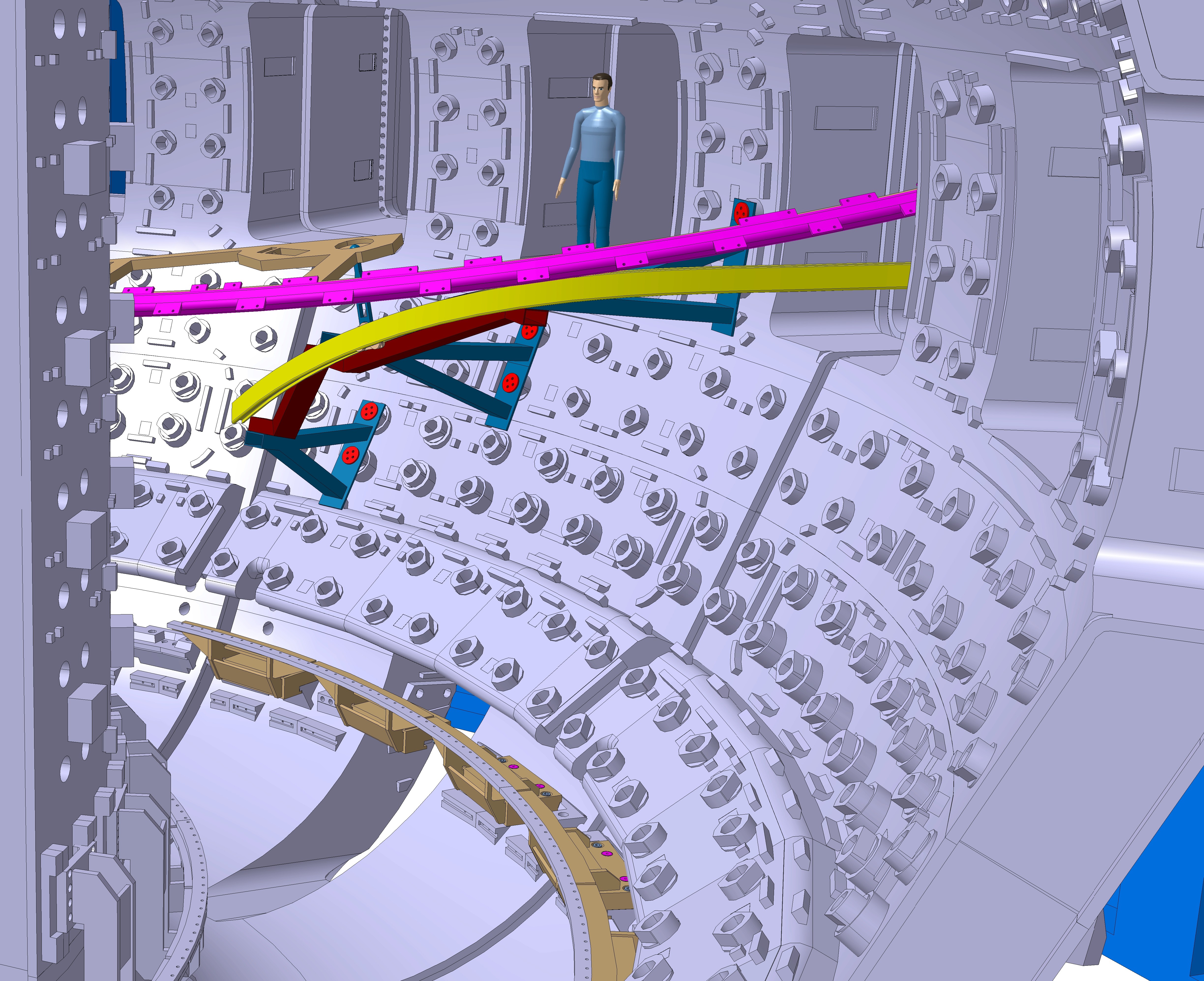
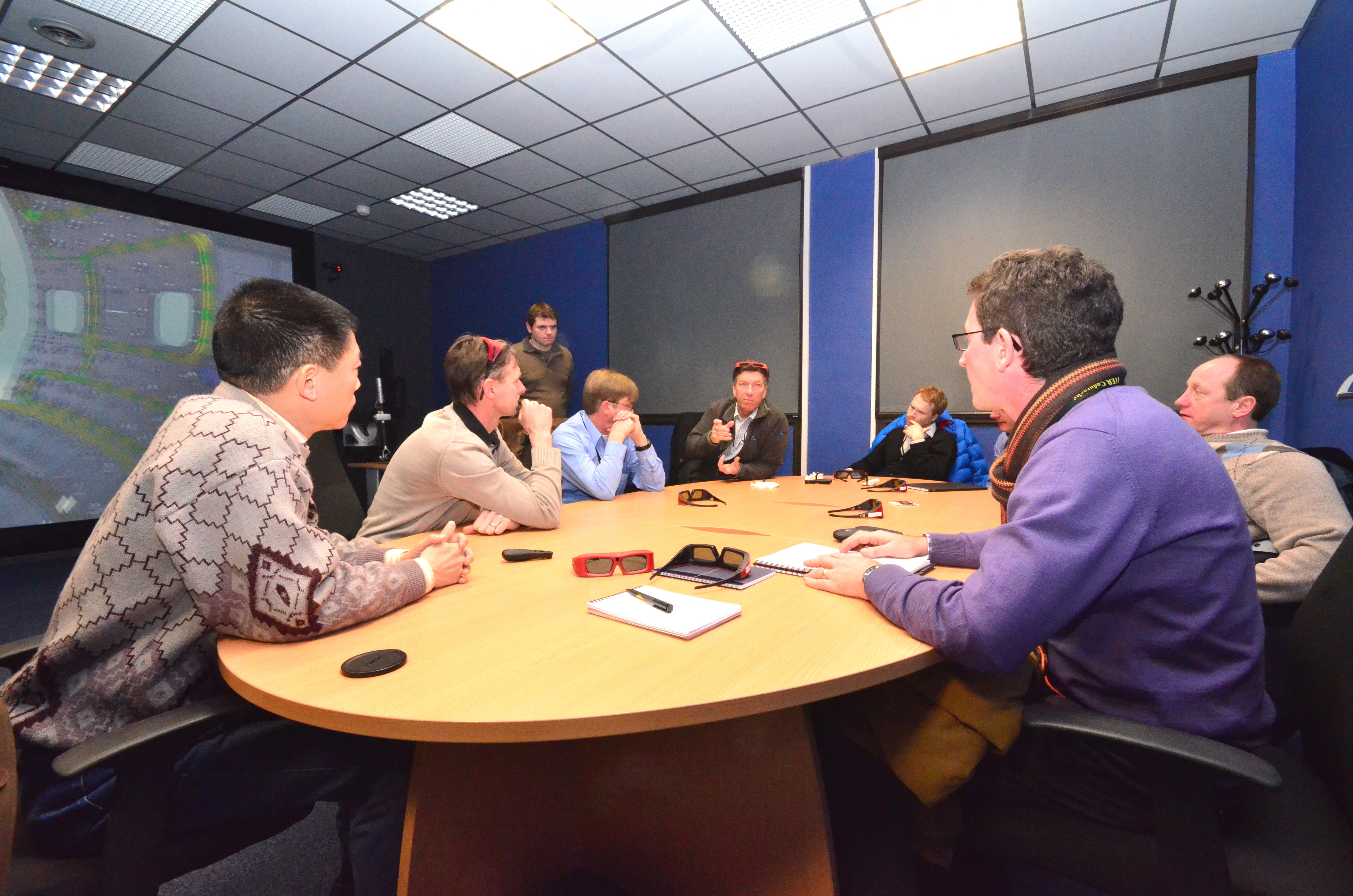
That is why the ITER in-vessel coil, assembly, and integration engineers meet regularly these days in the small 3D theatre next to the Tore Supra Tokamak, where CEA/IRFM has set up a virtual reality room. With the help of advanced 3D technology and simulations prepared by CEA in the framework of a contract with the ITER Organization, the engineers can study the movement of the VS coil segments along their integration trajectory and identify potential clashes.

"And these assembly simulations are only one part of the story," says Jens Reich, engineer in ITER's Design Integration Section. "Thanks to its capability to show adjacent interfaces, this 3D tool has significantly improved the overall integration situation inside the tokamak."

"Another advantage of the virtual reality room is that we get a much better appreciation of the real size of the components," adds Brian Macklin, "which is something we often forget as we look at models of huge components on our tiny CAD screens!"


return to the latest published articles