The technology advances
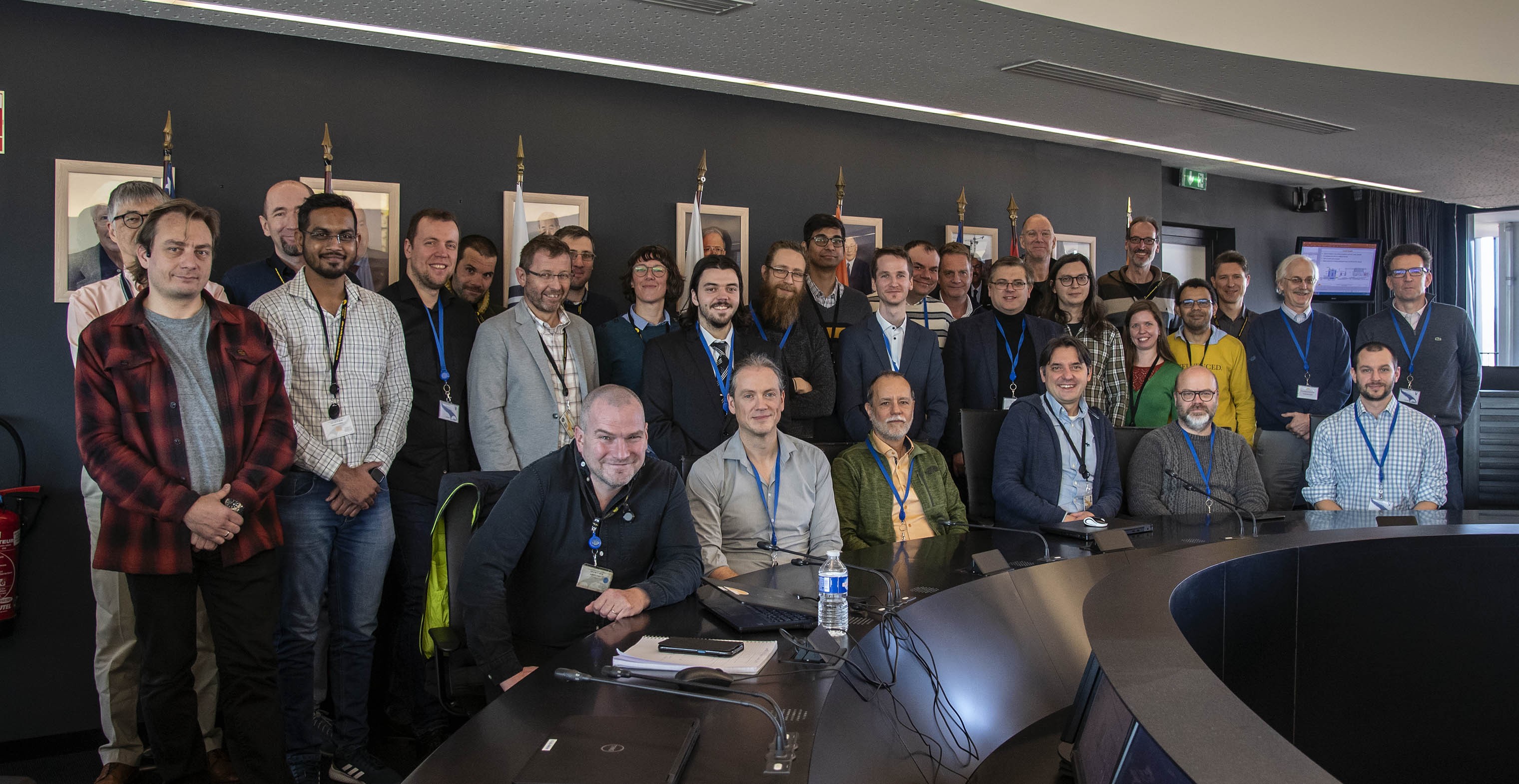
Experts from the ITER Members met for two days at ITER Headquarters to share the latest technological developments in the design of the ITER disruption mitigation system.

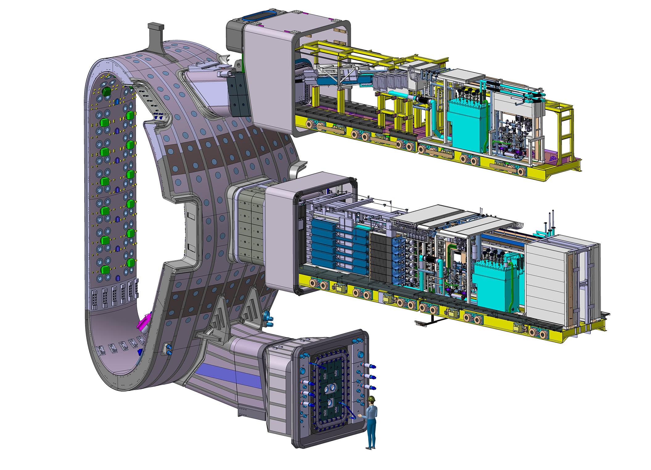
The disruption mitigation system will utilize shattered pellet injection to deliver massive amounts of protium and neon in the form of small ice fragments into the plasma to convert the energy into radiation. Despite having reached a high level of design maturity, as the above image demonstrates (showing part of the disruption mitigation system embedded into vacuum vessel sector #2), a number of technological challenges remain. These include a first-of-a-kind shattered pellet injection system (requiring an initial frozen pellet size seven times larger than on any other tokamak), material requirements (protium), environmental restrictions (radiation, limited space), and reliability and reproducibility requirements.
The ITER Organization has launched an extensive technology program to provide the necessary design validation and the development of novel concepts and components. This has led to worldwide collaborations with institutes and companies from the ITER Members and, thanks to the efforts of these collaborators over the last three years, the know-how and understanding of the complex processes involved in forming, launching, delivering and shattering pellets has seen a steep rise. For the first time since the start of the disruption mitigation project, technology experts together with the design team came together at ITER from 8 to 9 February 2023 for a vibrant meeting in which the latest achievements, covering a broad range of technological challenges, were presented and discussed.

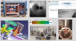
- Pellet formation: The low triple point and low heat conductivity of hydrogen (~15 times lower than the stainless steel formation cell) limits the heat removal capability during the desublimation process and makes the formation of large pellets (~3 cm x 6 cm) as required for ITER a challenge. Through different approaches and design solutions, the formation of such pellets was successfully demonstrated last year in three laboratories: Centre for Energy Research Budapest/Hungary, Département des Systèmes Basses Températures CEA-Grenoble/France, and Oak Ridge National Laboratory/US. An example of a cryostat showing the cold head where the pellet formation takes place, the pre-cooler and the thermal intercepts is shown below (figure 2a).
- Propellant gas suppression: The pellet is accelerated by a high-pressure gas puff. On its way to the plasma, the pellet will pass a component with internal barriers to allow the gas to expand, impeding it from further outflow into the flight tube. Computational fluid dynamic modelling is used to identify the best gas suppressor design for minimizing the amount of propellant gas entering the ITER vacuum vessel (see figure 2b, below). Otherwise, in case too much propellant gas arrives ahead of the pellet, the mitigation action with the shattered pellet would be jeopardized.
- Optical pellet diagnostic: It works like a speed camera except that it has only 50 microseconds to catch an image of the pellet passing the observation window at a speed of ~1,800 km/h (see 2c, below).
- Pellet flight accuracy: The pellets have to be launched with a precision of better than 1 cm over a distance of 6m for them to reach the shattering unit without colliding with the flight tube periphery. The trajectory precision is being assessed by firing pellets against a target plate (see 2d, below). Techniques (similar to muzzle brakes) to release the gas from the barrel will be employed to improve control over the pellet flight direction.
- Shattering: After just ~12 ms of flight time (it takes about 30 min to form a pellet!), the pellet trajectory is intersected by a structure where it shatters into a cloud of ice fragments which are then sprayed into the plasma. Different designs for this shattering structure are being investigated through simulations of this complex process (see 2e, below). The most promising configurations are then tested in the Support Laboratory at the Centre for Energy Research in Budapest, which contains a purpose-built shattering chamber with a large suite of dedicated diagnostics (see 2f, below).
- Alignment diagnostic: Ironically, the disruption mitigation system itself will suffer from the very plasma disruptions it is designed to mitigate, in the sense that potential movements of the vacuum vessel due to the electromagnetic forces during the disruption could lead to misalignment of the pellet flight lines. A 3D port plug alignment detector measuring any possible deviation from the default position has been developed and tested.
- Alternative concepts: As risk mitigation in the unlikely event that the baseline design fails to fulfil the key requirements the system must deliver, some R&D into novel and unusual alternative concepts are being developed within the technology program. As an example, a pellet formation device with a porous cold head is shown in figure 2g, below.