Lettres d'information

Choisissez ce que vous souhaitez recevoir :

Merci de renseigner votre adresse de messagerie électronique :

@

Votre adresse email ne sera utilisée que dans le cadre de campagnes d'information ITER Organization auxquelles vous êtes abonné. ITER Organization ne communiquera jamais votre adresse email et autres informations personnelles à quiconque ou dans le cadre d'informations commerciales.

Si vous changez d'avis, il vous est possible de vous désinscrire en cliquant sur le lien 'unsubscribe' visible dans vos emails provenant d'ITER Organization.

Pour plus d'information, veuillez consulter notre Politique de confidentialité.

Actu & Médias


Pour les actualités en français, voir la page Actus & Médias.
Superconducting joints

Making ends meet

The one-million-component ITER machine is far more complex than a space probe, a deep-sea submarine or a Mars rover. In order to fulfil its operational objectives it relies on the optimal performance of innumerable interdependent systems and devices, most of which, fortunately, can be tested prior to integration and commissioning. In a few cases however, such testing is impossible and responsible officers are faced with a daunting challenge: how to make sure that an untested component will perform as expected once the machine is up and running?

At the B2 (lower basement) level of the Tokamak Building, trained specialists are assembling the first feeder joint connecting the superconducting busbars from two feeder segments, the coil terminal box and the cryostat feed-through. This connection will feed 70 kA electrical current to toroidal fields coils #12 and #13. (Click to view larger version...)
At the B2 (lower basement) level of the Tokamak Building, trained specialists are assembling the first feeder joint connecting the superconducting busbars from two feeder segments, the coil terminal box and the cryostat feed-through. This connection will feed 70 kA electrical current to toroidal fields coils #12 and #13.
Answering this question is especially critical when it comes to assembling the superconducting joints that connect the high current feeding lines (busbar) to the magnets through the magnet feeders. Approximately 300 superconducting feeder joints need to be created as part of assembling the feeders, which are delivered in three segments to the ITER site.  

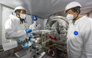
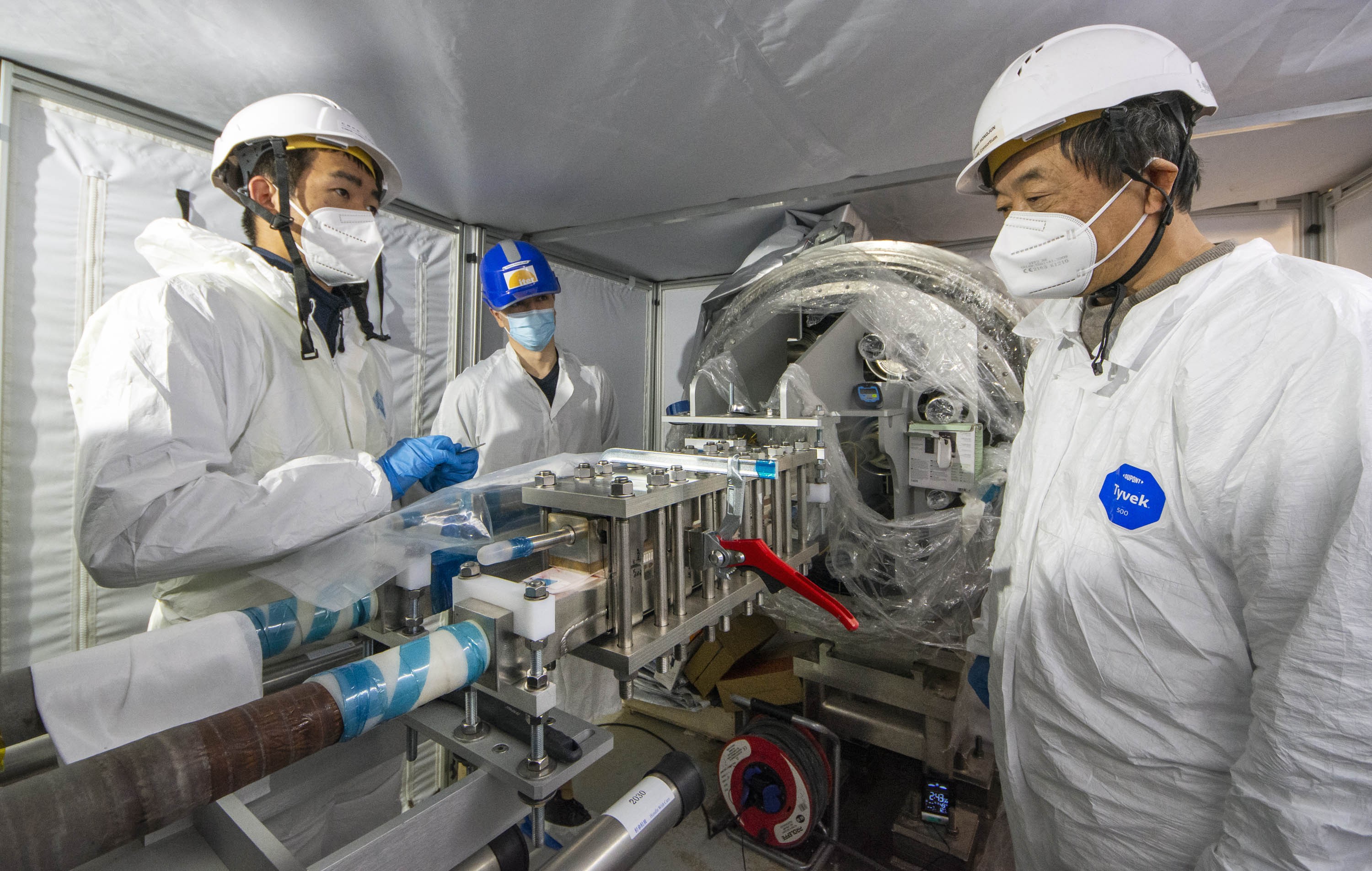
The joints need to be assembled in situ, once all the magnet feeder's elements are in place. What is expected from the joints is to oppose as little resistance to the current flow as possible: in theory, they should be as superconducting as the rest of the network that delivers up to 70 kA of electrical current to the magnets. In reality, what is needed is to limit the heating that would result from electrical resistance.

A few billionths of an ohm...

In order to generate as little electrical resistance as possible, the two ends of the superconducting busbar cables are compressed under heavy pressure in a box with a copper interface coated with a thin layer of the soft metal indium. This process allows for a large contact surface between the two ends of the busbar cable which reduces the electrical resistance to a negligible few billionths of an ohm—as a comparison, an extension cord for a home appliance has a resistance of a few hundredths of an ohm.

In addition to the ~300 feeder joints that need to be assembled on site, 12 very specific connections need to be created, also on site, for the superconducting "leads" that feed current to the central solenoid modules. For the US Domestic Agency (responsible for the procurement of the central solenoid) and the ITER Organization, the challenge was to design and realize joints that could fit into a cylinder no more than 44 mm in diameter due to the extremely small clearance between the central solenoid and the neighbouring toroidal field coils.

The solutions that were developed (see box) bring the electrical resistance to an extremely low value—in the nano-ohm (nΩ) range. Despite this small amount of resistance and resulting small amount of heat generated, the joints can still be called "superconducting."

However, once in place and assembled, a joint's electrical performance can only truly be put to the test at the ITER operating temperature (4 K, or minus 269 °C) and high-current (up to 70 kA), which will only be reached when the machine is commissioned. Detecting a problem at this stage, however, would lead to loss of time for repairs—a situation the team is determined to avoid by developing qualification programs for the technicians who will realize joint assembly and establishing precise procedure controls and step-by-step acceptance tests on samples and mockups produced throughout the qualification program to demonstrate technician skill.

Over the past decade, different ITER Domestic Agencies have engaged in the development of the feeder component that fell within their scope. As far as feeder joints are concerned, the Institute of Plasma Physics of the Chinese Academy of Sciences (ASIPP) has been on the front line of research and development. With the close support of the ITER Organization feeder team and feedback from the ITER-CEA MIFI laboratory, ASIPP produced and qualified the first feeder joint sample in 2016. Qualification tests were performed in the Swiss facility SULTAN—the only installation in the world capable of imitating, within a significant magnetic field, the current intensity and temperature of ITER operational conditions. In that punishing environment the performance of the joints was confirmed.

As machine assembly is progressing on the ITER site, the time has now come to prepare for the actual implementation of the joints. A multiyear training program has already qualified several specialists from the TAC1 assembly teams. New samples, similar to those realized during the qualification stage, were produced and again successfully tested in the SULTAN facility.

In the SELFIE installation, joint production proof samples will be tested in temperature and current intensity that are representative of ITER operating conditions. The 6.2-metre-tall installation, of which only the upper part is visible in this image, is located next door at CEA-Cadarache. Its superconducting transformer, power supply and entire control and protection system was designed and built at the University of Twente in the Netherlands in collaboration with the Foundation SuperACT. The system was successfully commissioned in January 2022. Photo Christophe Roux - CEA (Click to view larger version...)
In the SELFIE installation, joint production proof samples will be tested in temperature and current intensity that are representative of ITER operating conditions. The 6.2-metre-tall installation, of which only the upper part is visible in this image, is located next door at CEA-Cadarache. Its superconducting transformer, power supply and entire control and protection system was designed and built at the University of Twente in the Netherlands in collaboration with the Foundation SuperACT. The system was successfully commissioned in January 2022. Photo Christophe Roux - CEA
It is of paramount importance that the qualified specialists maintain a stable and verifiable level of performance throughout the four years that joint assembly operations will last. In this perspective, and within the framework of the Site Support Agreement, the ITER Organization and the French Alternative Energies and Atomic Energy Commission (CEA) have recently built an installation called SELFIE (for "self-field") that will test the production proof samples that every qualified specialist will be required to produce.

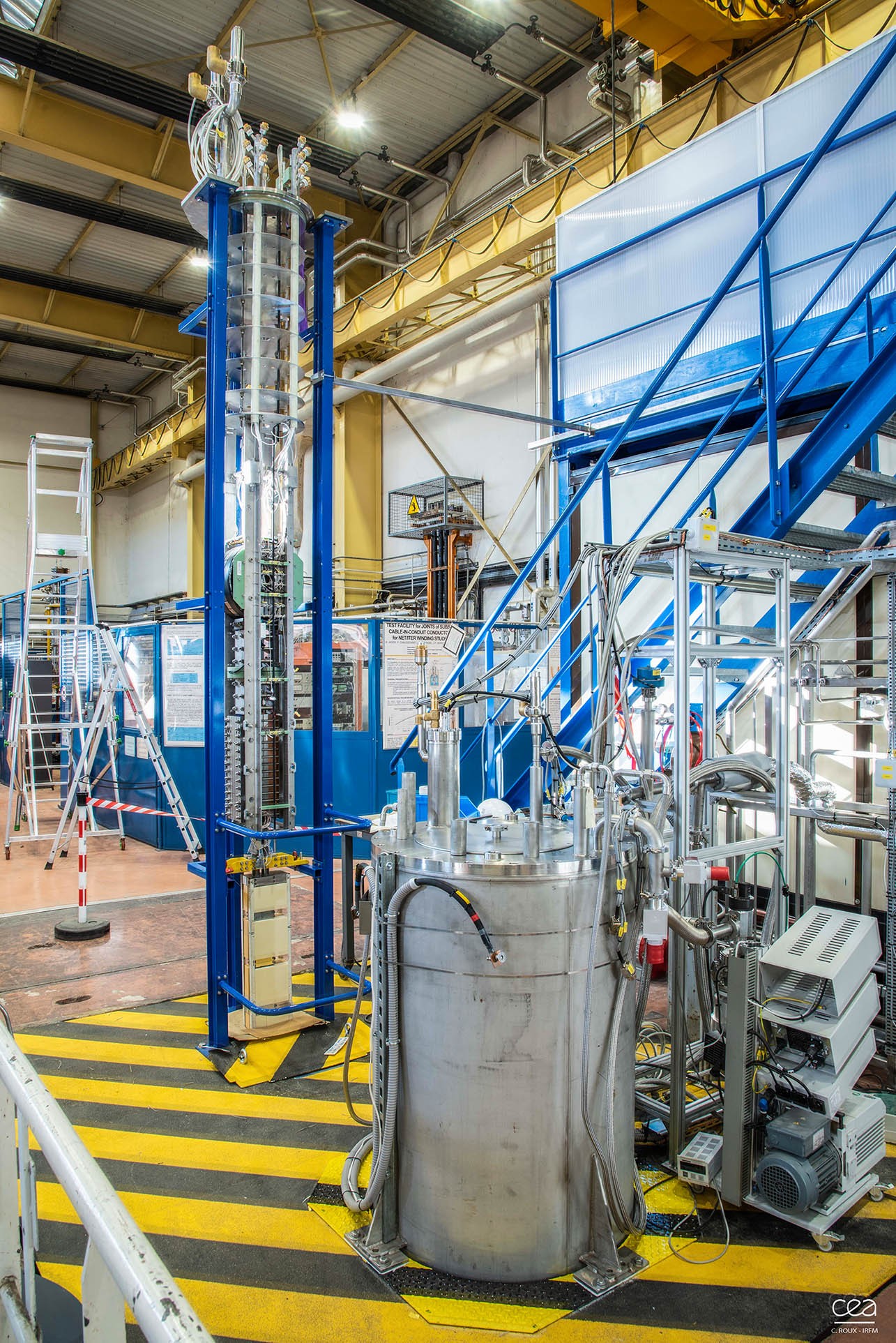
Located at CEA-Cadarache on the other side of the ITER fence, SELFIE can be described as a small, close-to-home SULTAN. The main difference between the two facilities is that SELFIE is operating without an external magnetic field whereas SULTAN is equipped with a magnet that delivers a very strong field (4 tesla). In SELFIE the magnetic field is self-generated by the electrical current in the sample—hence the installation's name.

The SELFIE installation is encased in a 6.2-metre-tall, 0.86-metre-in-diameter cryostat hosting a thermal shield and a tank filled with liquid helium at 4 K. The helium inner tank accommodates both the superconducting transformer that delivers the 70kA current and the 3.60-metre-tall "sample" to be tested.

The conditions to which the samples will be submitted in SELFIE are similar to those the actual joints will face in the ITER coil termination boxes. The only parameter missing is the background magnetic field, but its influence is not essential to checking the baseline resistance value.

As actual joint assembly operations progress, the qualified specialists will be required to produce test samples every six months in order to verify that their performance remains at top level—an ingenious and efficient way of "testing" what cannot be tested.


return to the latest published articles